EN
EN

An architectural opening can be accurate to the millimeter and still be a poor production dimension for a custom size LED screen. Once the site dimensions are already known, the important work changes from measurement to translation. The available width and height must become complete LED modules, practical cabinet rows and columns, a serviceable support layout, and an intentional edge condition. A good grid does not force electronics into every remaining millimeter. Instead, it finds the cleanest manufacturable display inside the architectural space.
This distinction matters because a narrow leftover strip can look insignificant on a drawing while creating disproportionate engineering work. A balanced reveal may need only a simple finishing detail. Removing the same reveal with a special cabinet can affect mounting points, wiring, spare parts, structure, and maintenance. The aim of cabinet-grid planning is to see that trade-off before the quotation becomes a production layout.
Build a Manufacturable LED Cabinet Grid from the Measured Opening
Once the opening has been measured, its width and height become boundaries rather than automatic factory dimensions. LED hardware does not behave like a sheet material that can stop at any convenient point. The display grows through physical module increments, and those modules must sit inside workable cabinets. If the smallest clear width, depth limit, or service clearance is not yet confirmed, complete the custom size LED screen measurement check before fixing the grid.
For installations requiring more flexibility than a simple standard configuration, the Custom LED Display direction provides the relevant project path. Even then, customization does not need to make every component unique. In many successful layouts, the electronic core stays regular while the surrounding architectural detail handles the remaining difference.
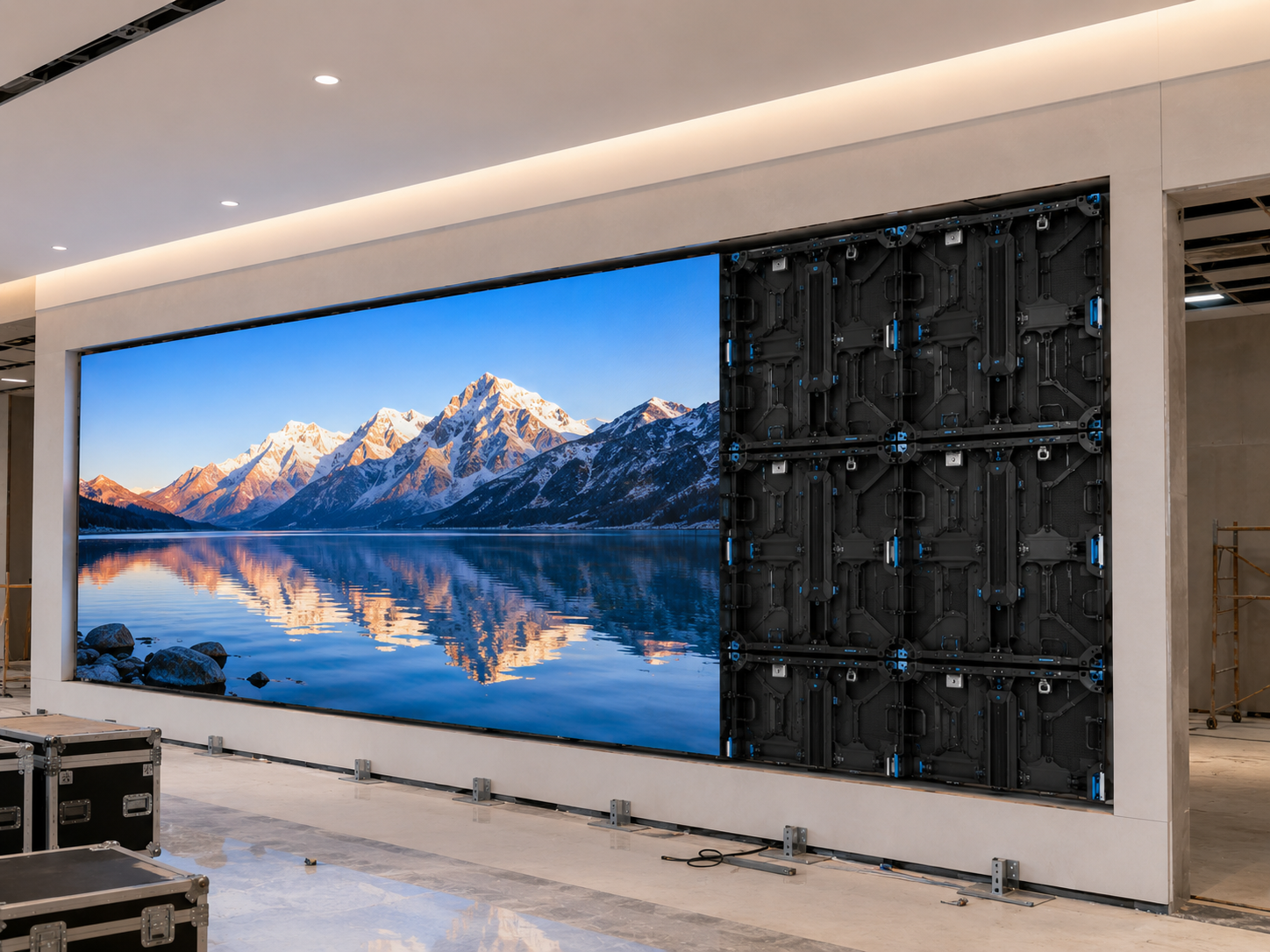
Complete cabinets sit inside the architectural boundary. The remaining edge can then be evaluated instead of hidden.
Practical reading: a small balanced edge gap can be easier to finish than one narrow position-specific cabinet.
Start with complete modules, not the last few millimeters
The useful starting question is how many complete modules can fit horizontally and vertically. A module contains a defined PCB boundary, pixel matrix, connectors, mounting points, and electronic layout. Those elements make the physical module size meaningful during manufacturing.
Once the module matrix is sensible, the next step is grouping those modules into cabinets. This second level matters because the cabinet determines how the display is handled, fixed, wired, aligned, and serviced. A screen can have a clean module count yet still use an awkward mechanical layout if the cabinet grouping is poorly resolved.
The goal is not simply to maximize the number of modules inside the opening. Rather, the goal is to find a repeated matrix that leaves a manageable perimeter and keeps the mechanical system understandable. That difference turns a dimension exercise into an engineering decision.
Worked example: turn one usable opening into a cabinet grid
Assume the verified usable opening is 4,100 mm wide by 2,600 mm high after the site team has identified the real hard boundaries. For an illustrative 500 × 500 mm cabinet option, eight columns and five rows create a 4,000 × 2,500 mm cabinet grid.
5 × 500 = 2,500 mm
2,600 − 2,500 = 100 mm
Top 50 mm / Bottom 50 mm
Important: this example explains the arithmetic, not a universal clearance rule or product recommendation. The manufacturer and project team must confirm the selected cabinet family, module compatibility, assembly tolerance, support detail, installation allowance, finishing build-up, and service path before production dimensions are approved.
The remainder from that calculation is not automatically a problem. A small value may become a controlled reveal or trim condition. A much larger value may suggest another cabinet format deserves comparison.
This is also why rounding should be treated carefully. Rounding an architectural dimension to the nearest convenient display size may hide the fact that the cabinet count changed. It is better to show the actual cabinet matrix and the resulting edge gap so the trade-off remains visible.
Cabinet count changes more than the final width
Adding one cabinet column changes the physical width, but the effect continues beyond the front elevation. Another column adds cabinet joints, fixing positions, power and signal connections, structural references, and installation work. The same applies when another cabinet row is introduced vertically.
Meanwhile, fewer larger cabinets can reduce the number of joints while changing handling and support conditions. A larger physical unit may be convenient in one fixed installation and less convenient in another restricted site. For that reason, cabinet size should be evaluated as part of the installation system rather than as a dimension alone.
Compare real cabinet increments before moving into custom edge hardware
Different cabinet formats create different dimensional rhythms. A smaller cabinet increment can offer more combinations across a fixed opening. A larger format creates fewer joints, although the jump from one valid grid width to the next becomes larger.
The two real product references below illustrate that dimensional principle only. They are not interchangeable specifications or automatic recommendations. Pixel pitch, module arrangement, indoor or outdoor use, service direction, cabinet construction, support method, and project application must be checked separately before either format enters a quotation.
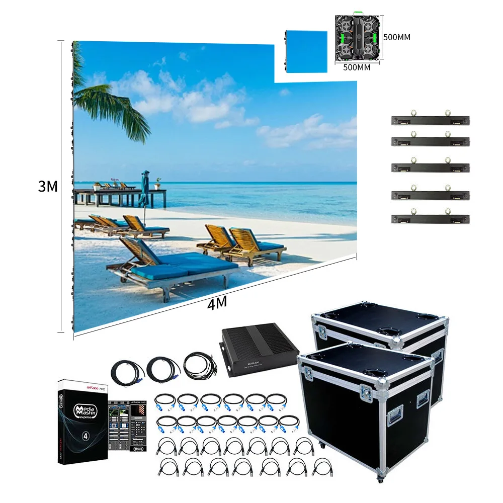
500×500 Cabinet Reference
A 500 mm increment can create more possible width and height combinations inside a fixed architectural boundary. This linked outdoor product is a dimensional reference; its pitch, module arrangement, support, service access, application, and joint count still require project review.
View 500×500 Cabinet
960×960 Cabinet Reference
A 960 mm repeating cabinet can create a simpler fixed-installation matrix in a suitable project. Each added unit also changes the total width or height by a larger amount. Treat this as a separate supported cabinet route, not as a direct substitute for the 500 × 500 reference.
View 960×960 DisplayWhy an Exact Architectural Opening Is Not Automatically a Production Screen Size
Architectural drawings use precise dimensions for good reason. Recesses, stone panels, wall finishes, metalwork, millwork, and structural openings all need clear coordination. Yet that precision does not mean the same number should pass directly into LED production.
The building dimension is continuous. It can end wherever the project drawing requires. An LED display is granular. Its physical size changes when a complete module or cabinet is added or removed. Those two systems only line up perfectly when the architectural dimension happens to match the selected LED grid.
The line can terminate at the required project measurement.
The line advances one complete electronic or cabinet increment at a time.
A CAD rectangle can hide the real manufacturing conflict
On a front elevation, almost any rectangle can be drawn to fit another rectangle. The conflict becomes visible only when module boundaries and cabinet joints appear inside that outline. A width that looks perfectly reasonable on a plan may finish halfway through a standard cabinet.
At that point, the design has several choices. The active LED width can move slightly. The grid can be centered with a controlled reveal. Another supported cabinet format or orientation can be tested. Alternatively, a special edge solution can be engineered if the architecture genuinely requires a tighter visual boundary.
None of those options should be hidden inside one overall dimension. The project becomes easier to coordinate when the difference is shown directly and the chosen solution has a clear reason.
The smallest leftover strip can create the largest change
A narrow remainder often attracts more attention than it deserves. A complete cabinet matrix may leave only a modest strip on one side of a recess. Visually, that strip can look like a simple problem to eliminate.
Internally, however, reducing the cabinet width can affect the module arrangement, receiving hardware, power component space, connectors, mounting holes, rear structure, and cable routing. One visually small change can therefore introduce a new mechanical part type across the full project documentation.
This does not make narrow custom cabinets inherently wrong. It means the architectural benefit should justify the engineering consequence. If a balanced 20 or 30 mm reveal produces the same visual result as a complicated edge enclosure, the simpler approach may deliver more value over the full service life.
Does the remaining strip create a real architectural problem, or does it only look like unused space on the engineering drawing? If a clean finishing detail can absorb it, the electronic system may not need to change at all.
Visible LED size and cabinet size should not share one label
The phrase “screen size” is often too broad for an architectural installation. The visible LED face has one width and height. The complete cabinet matrix has another physical boundary. Meanwhile, the finished architectural opening may include a bezel, trim strip, shadow gap, removable access panel, or cladding return.
If all three are described with one overall number, different teams can read the same drawing differently. AV planning may assume the dimension represents active image area, while fabrication may treat it as the outside of the cabinets. The finishing team may expect the same dimension to represent the clear opening.
Keeping the layers separate removes that ambiguity early. The active LED surface can remain centered. The cabinet structure can keep the necessary clearance. The finish can then close the remaining perimeter without changing the electronic face.
When the Grid Does Not Divide Cleanly, Decide What Should Change First
Once the remainder is visible, the next decision should follow the cost of changing each layer. A small visual adjustment is usually easier to manage than a unique electronic edge. A trim change is often easier than developing another cabinet family. That difference creates a useful order of review.
The purpose of the order is not to prevent custom engineering. Instead, it protects standard parts until the project has a clear reason to move beyond them.
Adjusting the visible area can protect the whole electronic system
When the architectural concept allows some dimensional flexibility, a modest change to the active area can remove a surprising amount of complexity. A complete grid may leave a narrow border, but every cabinet remains repeatable and every module stays inside its intended mechanical system.
This approach works especially well when the grid can remain centered. Equal left and right gaps usually read as a deliberate design detail. Equal top and bottom conditions can provide the same visual discipline where the installation allows them.
The key is proportional judgment. A small change in LED width may be almost invisible at normal viewing distance, while the removal of that difference could require an entirely new cabinet. The drawing should make that trade-off visible instead of assuming the tighter fit is automatically better.
Trim can be an engineering solution rather than decorative cleanup
Some architectural openings are already fixed by surrounding stone, metalwork, wall panels, furniture, or another finish. In those cases, changing the opening is no longer practical. The LED system still does not need to occupy every available millimeter.
A bezel, recessed reveal, shadow line, removable finishing strip, or coordinated cladding return can bridge the remaining space. When designed intentionally, that edge can make the LED face look more integrated rather than smaller.
Service access remains important. A trim profile that overlaps a module edge may need to be removable. A frame should not hide a fixing point that must be reached later. The final architectural detail should therefore be reviewed together with the maintenance direction rather than designed after the hardware is locked.
Another supported cabinet format can sometimes solve the gap without custom hardware
Before a special edge cabinet is introduced, compare the proposed grid with available LED Screen Panels and review the broader custom LED display versus standard panel decision. The purpose is not to force every project into one panel format. It is to check whether an existing modular route gives a cleaner dimensional result before new hardware is commissioned.
This is particularly useful when one cabinet family leaves a large remainder while another produces a balanced edge. The resulting installation may stay fully standard without sacrificing the intended architectural proportion.
Once those routes have been checked, a special cabinet becomes a much more focused request. Engineering can see the exact dimension that cannot be resolved with a supported matrix. The conversation then moves from “make the screen custom” to “solve this specific edge condition.”
| Possible adjustment | Main value | Main check before approval |
|---|---|---|
| Change active width or height slightly | Preserves complete modules and repeated cabinets. | Visual proportion and architectural alignment. |
| Use trim or a reveal | Absorbs a small perimeter remainder without changing electronics. | Appearance, removability, and service path. |
| Change cabinet format or orientation | May improve divisibility while retaining existing hardware. | Joint count, handling, structure, and maintenance. |
| Develop a special cabinet | Can satisfy a genuinely fixed architectural condition. | Modules, mounting, wiring, spares, structure, and service. |
Reduce Edge Exceptions Before They Become Installation and Maintenance Problems
A clean cabinet matrix creates value long after the front elevation is approved. Repeated units make support positions easier to coordinate, power and data paths easier to organize, spare parts easier to identify, and maintenance procedures easier to repeat.
Special parts can still be appropriate, particularly in demanding architectural integrations. The important point is to know how many exceptions the finished system contains and why each one exists.
Repeated widths, repeated fixing logic, and common spare positions.
The edge may now require another cabinet, fixing detail, cable route, or spare record.
Standard LED modules should not be treated like tiles that can be cut to fit
From the front, an LED module can look like a simple rectangular tile. Internally, it is a complete electronic assembly. The LED packages, PCB traces, drivers, connectors, mounting features, and pixel matrix all follow the physical design of that module.
Cutting through a standard module would therefore be very different from trimming a decorative panel. The term “cut module” can make a complex electronic change sound deceptively simple. A non-standard edge should instead be treated as a purpose-engineered component that requires project confirmation.
A different cabinet shell can regroup complete standard modules or change the mechanical envelope. It cannot create an arbitrary active LED width when the required boundary falls through a standard module. Changing that active pixel boundary may require a purpose-designed module or PCB, along with separate confirmation of resolution, calibration, wiring, spares, testing, and replacement support.
This distinction improves quotation clarity. Rather than requesting a cut piece at one side, the drawing should state where the selected module and cabinet grid stops, identify the unresolved edge dimension, and ask whether the feasible solution is a different cabinet grouping, a purpose-designed electronic edge, or an architectural finish. The production method should not be assumed before engineering review.
Irregular cabinets often create irregular support details
A repeated cabinet matrix naturally supports repeated rail spacing and predictable fixing positions. The structure can follow the same rhythm as the LED wall. Once a narrow edge cabinet appears, that structural rhythm may change at the perimeter.
The edge can need another bracket, an offset rail, a local support member, or a different fixing position. Those details are perfectly manageable when the architecture requires them. They become less attractive when they exist only to remove a small reveal.
The same principle applies to cabinet depth. A special cabinet with a different rear profile may need an offset support while the front LED plane still has to align with every neighboring cabinet. This creates another reference dimension for fabrication and installation.
Spare-part simplicity begins with the grid drawing
A repeated cabinet system creates useful interchangeability. One spare cabinet type can cover several positions. One module type can serve much of the active wall. Common cable layouts make troubleshooting easier to understand.
A unique edge changes that picture. The left edge may need a different cabinet. The right edge may need another mirrored version. A special top or bottom unit may add another part type. If the electronic arrangement changes too, a dedicated module may also be required.
None of these parts are automatically unacceptable. However, they should appear deliberately in the spare strategy. A quotation that lists only total cabinet quantity can hide the fact that several units are not interchangeable.
Maintenance needs a removal path, not just enough installed space
A cabinet can fit neatly inside a recess and still be difficult to service. The installed position shows where the component sits. Maintenance planning asks whether that component can actually move out of the wall using the intended service method.
Front-service layouts need usable access across the LED face. A trim profile that overlaps module edges may need to be removable before service starts. Rear-service layouts need enough access behind the cabinets for the components that require attention.
Edge details deserve particular attention because architecture often closes around the display there. A beautiful finishing line that blocks module removal or a cabinet release point creates a predictable maintenance problem. Grid and trim planning should therefore happen together.
Cable routes should stay as repeatable as the cabinet pattern
Standard cabinets usually allow a repeated power and signal path. When a special cabinet changes internal component positions, the connector locations may move as well. That can affect cable lengths, service loops, entry directions, and routing around the edge.
The cabinet-grid stage does not need to finalize the complete electrical design. Still, the proposed edge should leave a believable path for power and data. A geometry that only works from the front can create avoidable difficulties once the rear connections are considered.
Electrical protection, grounding, structural verification, local compliance, and similar project requirements still need confirmation for the actual installation. Grid planning should identify the relevant interfaces without assuming one universal requirement applies everywhere.
The better question is whether the special edge solves enough architectural value to justify another cabinet type, another support condition, another spare position, or another service detail.
Put Cabinet Grid, Visible Area, and Trim Gap on the Quotation Drawing
A quotation becomes much easier to review when the dimensional logic appears before price becomes the main discussion. One overall width and height cannot explain whether the dimensions represent the LED face, the cabinet assembly, or the final architectural opening.
Three groups solve most of that ambiguity: Cabinet Grid, Visible Area, and Trim Gap. Each answers a different project question. Showing them together makes the effect of every edge decision visible.
Cabinet Grid shows what the project will physically receive
The grid should identify cabinet columns and rows rather than only total quantity. A count of 24 cabinets could describe an eight-by-three matrix, a six-by-four matrix, or a layout that mixes several cabinet sizes. Those arrangements are not mechanically equivalent.
Overall cabinet-grid width and height should accompany the count. The drawing can also identify cabinet orientation, service direction, structural reference, and any position that uses a different cabinet type.
This turns the quotation from a square-meter statement into a physical assembly concept. It also creates a clear basis for checking the structure before final fabrication drawings are issued.
Visible Area shows what part of the assembly actually displays content
The active LED width and height should remain separate from the complete mechanical envelope. Module columns and rows can be recorded alongside those dimensions because they explain how the visible surface was created.
Where the engineering package requires it, the resulting physical pixel matrix can also be recorded after the selected configuration is confirmed. Still, that value should remain an output of the physical grid in this discussion.
Content aspect ratio and native media-resolution planning are separate decisions. They may influence another stage of display design, but they should not be mixed into the manufacturing-grid problem when the immediate question is whether complete cabinets and modules fit the opening cleanly.
Trim Gap explains where the architectural remainder goes
The perimeter should be recorded side by side rather than as one vague allowance. Left and right values show whether the screen sits centrally. Top and bottom values show how the grid relates to ceilings, floors, surrounding finishes, or another architectural reference.
The drawing can also state what the gap is intended to become. One project may use removable trim. Another may use an intentional shadow line. Elsewhere, the dimension may remain a field-adjustment zone around a fixed structural frame.
No universal trim dimension should be assumed. The appropriate edge depends on the selected cabinet system, finishing design, installation method, service direction, and actual site condition. The important part is that the value appears openly on the drawing.
A useful pre-quotation field set
Smallest verified opening width and height
Measurement unit and dated site photos
Indoor or outdoor application
Target pixel pitch
Maximum installation depth
Planned service direction
Mounting condition
Whether the active LED size may change
Whether a trim or reveal is acceptable
Fixed architectural edges or obstructions
Module columns and rows
Cabinet columns and rows
Cabinet-grid width and height
Active LED width and height
Service direction
Special cabinet positions, if any
Left gap
Right gap
Top gap
Bottom gap
Trim / reveal concept
Open edge questions requiring confirmation
A special part should be visible instead of disappearing into the total quantity
When a non-standard cabinet is genuinely required, the quotation drawing should identify it directly. A position ID and short note can prevent later confusion about which cabinet belongs at which edge.
The drawing can also note whether the special part changes the module arrangement, mounting detail, service method, wiring path, or spare requirement. This does not need to become a long technical manual. A concise register is enough to show that the part is intentional.
This small amount of clarity is useful during quotation comparison as well. One proposal may use a standard grid and wider trim. Another may use a tighter edge with several position-specific cabinets. Without identifying those differences, the two quotations may look more similar than they really are.
When the choice is close, show two grid options
A difficult opening does not always need one solution immediately. In many cases, showing two compact grid options communicates the engineering trade-off more clearly than a long explanation.
One option can preserve standard cabinets and accept a wider reveal. The second can reduce that reveal by using a special edge. The comparison should then focus on what changes behind the LED face, not only on the few millimeters gained at the perimeter.
Cabinets: repeated formats
Structure: regular support pattern
Spares: higher interchangeability
Edge: larger controlled reveal
Cabinets: one or more special positions
Structure: additional local coordination
Spares: dedicated part planning may be needed
Edge: smaller architectural reveal
If the tighter option produces a meaningful architectural improvement, the extra engineering may be justified. If the difference is almost invisible in the finished installation, the standardized grid can offer a cleaner manufacturing and maintenance path.
FAQ
Why can an exact architectural opening not always become the exact finished LED dimension?
The opening can end at any measured architectural dimension, while the LED system grows through complete modules and cabinets. The measured width or height may therefore fall between two practical grid combinations.
The difference does not mean the site dimension is wrong. It means the architectural space must be translated into a manufacturable electronic and mechanical matrix. A small active-size adjustment or controlled edge finish can often resolve the difference without changing the standard LED hardware.
Can a narrower custom cabinet remove any remaining edge gap?
Not automatically. A custom cabinet may regroup complete modules or change the mechanical enclosure, but the active LED face still follows complete module and pixel boundaries.
If the required edge falls through a standard module, the options are to adjust the active area, use a controlled trim or reveal, select another supported module and cabinet system, or request a purpose-designed electronic edge. The last route needs separate engineering and spare-part confirmation.
When an edge gap remains, should the LED area, trim, or cabinet change first?
A small visible-size adjustment is usually the least disruptive route when the architectural concept allows it. If the opening is fixed, a balanced trim or reveal can be reviewed next.
Another supported cabinet format or orientation can then be compared. A special cabinet or purpose-designed electronic edge makes more sense when those simpler options cannot satisfy an important architectural requirement. This order keeps standard parts intact for as long as practical.
Why can non-standard edge cabinets increase structural and maintenance complexity?
A special cabinet can bring different fixing points, internal component positions, cable routes, or rear dimensions. The surrounding support may also need a local bracket or offset that does not appear elsewhere in the display.
Spare planning can become more position-specific as well. For that reason, special cabinets should be clearly identified on the drawing rather than hidden inside the total cabinet count.
What do Cabinet Grid, Visible Area, and Trim Gap each solve on a quotation drawing?
Cabinet Grid shows what physical cabinet matrix will be manufactured and installed. Visible Area shows the active LED image surface. Trim Gap records the remaining space between the display system and the architectural boundary.
Separating these dimensions prevents one “overall size” from carrying several meanings. It also makes a standard-grid proposal easier to compare with a tighter but more customized alternative.
Lock the Cabinet Logic Before Locking the Finished Edge
Once the opening dimensions are known, the project no longer needs another generic measurement discussion. It needs a cabinet-grid proposal that shows how complete modules and cabinets occupy the available space.
That proposal should make the trade-off visible. A slightly smaller active face with balanced trim may preserve standard hardware. Another supported cabinet format or orientation may create a cleaner fit. Where the architecture truly demands it, a special mechanical or electronic edge can then be engineered with its consequences understood.
Three practical actions keep the project moving without turning the review into a long specification exercise:
- Provide the smallest confirmed opening dimensions and target pixel pitch. Use one measurement unit and add dated site photos, indoor or outdoor use, maximum depth, service direction, mounting condition, active-size flexibility, acceptable edge finish, and fixed architectural constraints.
- Request a cabinet-grid feasibility layout. The drawing should show module rows, cabinet columns, active LED dimensions, and four-side edge gaps.
- Compare the standard-grid route with any special-edge route. The tighter fit should be approved only when its architectural value justifies the extra mechanical or service complexity.
Request a Cabinet Grid Feasibility Review
Submit the smallest verified opening width and height in one measurement unit, together with dated front and side photos, indoor or outdoor use, target pixel pitch, maximum installation depth, service direction, mounting condition, fixed architectural edges, and whether the active LED size or trim line may change.
Ask for two layouts where practical: a repeated standard grid and any tighter special-edge route. Each feasibility layout for the proposed custom size LED screen should show module rows and columns, Cabinet Grid, Visible Area, left, right, top, and bottom Trim Gap, cabinet types, service direction, and every position requiring special mechanical or electronic engineering. Compare the architectural gain with the added structure, wiring, spare-part, and maintenance consequences before production dimensions are locked.
Request Cabinet Grid Review