EN
EN

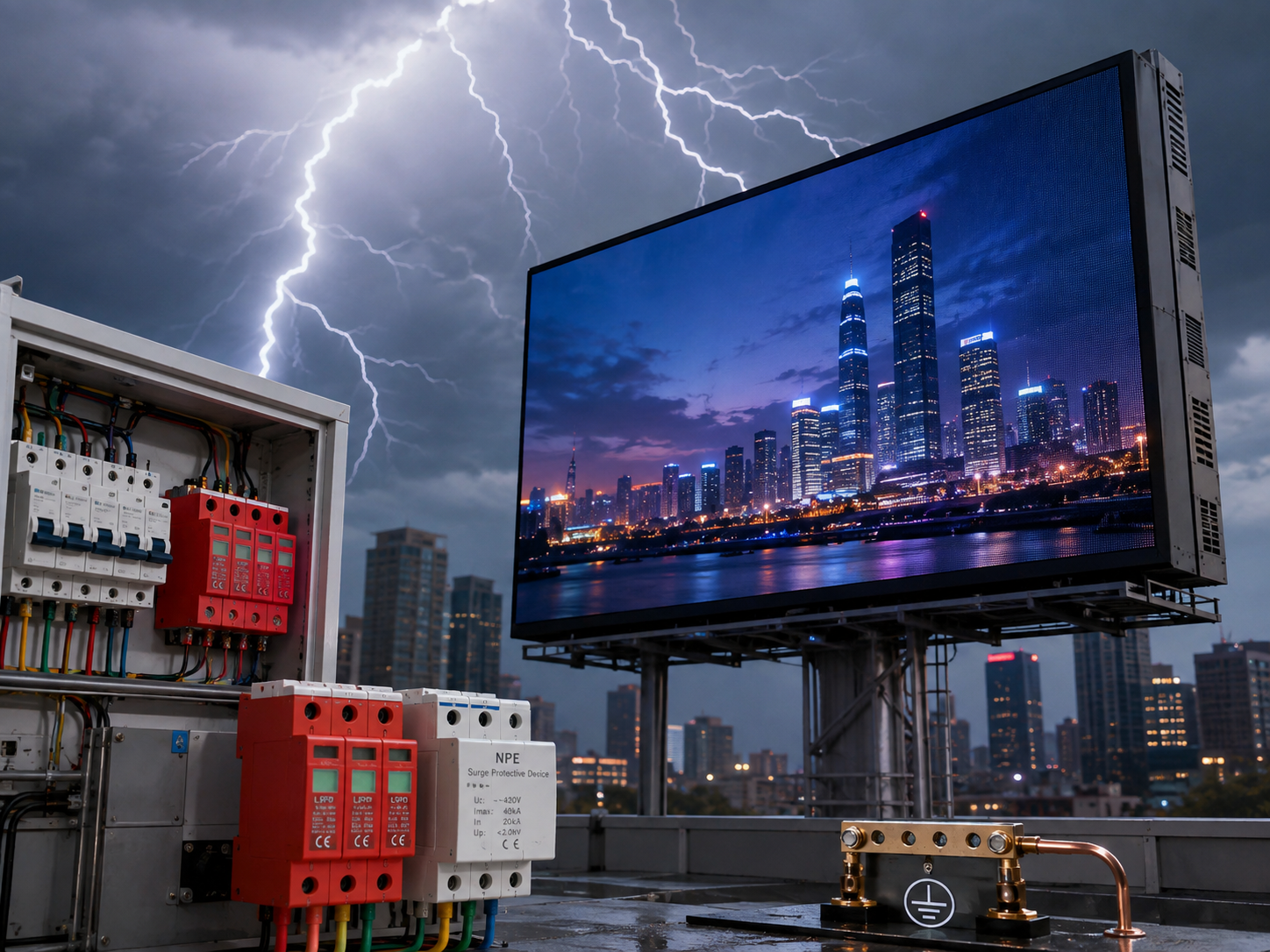
A reliable outdoor LED screen grounding and surge protection review should cover more than enclosure protection. When evaluating an outdoor led screen supplier, the electrical discussion should connect mains power, distribution equipment, metal structures, cabinet electronics, control hardware, communication links, and the site earthing system. The practical question is not simply whether the display can operate outdoors, but whether every conductive path and protection boundary is defined before installation drawings are frozen.
The clearest way to review the installation is to treat the supply origin, main distribution point, local LED distribution cabinet, screen structure, control location, and external cable routes as connected boundaries. This guide stays focused on those electrical relationships. For separate project questions, see the guides to IP rating and weatherproofing, brightness and power trade-offs, and coastal corrosion, drainage and heat control.
Outdoor LED Screen Grounding and Surge Protection Go Beyond Enclosure Protection
An Outdoor LED Display is part of a site electrical system rather than an isolated appliance. The screen may receive power from a building switchboard, a dedicated outdoor distribution point, or a remote feeder. Control signals may arrive from another room or another structure, crossing different electrical environments before they reach the LED cabinets.
An enclosure rating answers a specific ingress question. It does not describe fault-current paths, protective-conductor continuity, the relationship between structural metal and the earthing system, or the effect of a transient entering through a long power or copper signal cable. Start the electrical review with the whole installation diagram rather than a single cabinet specification line.
The useful question is where electrical energy can travel
Outdoor screen faults rarely respect catalogue boundaries. For example, a local LED distribution cabinet may be close to the display while the main switchboard sits far inside a building. At the same time, the sending equipment may be powered from a different room. A conductive signal cable can then create another path between equipment groups that looked separate on the mechanical drawing.
Instead of asking whether one component is protected, the project team should trace power, protective conductors, structural metal, and communication links from end to end. This approach exposes missing interfaces early. It also makes responsibility clearer between LED engineering, the integrator, the electrical contractor, the structural team, and the qualified local professional responsible for final compliance.
Keep three electrical questions separate
Grounding and bonding, surge protection, and structural lightning protection interact, but they are not interchangeable. Grounding and bonding address the relationship between conductive parts and the approved earthing arrangement. Surge protection addresses transient overvoltage on electrical or signal paths. Structural lightning protection addresses a broader site risk and may include air-termination, down-conductors, separation, bonding, and other measures defined by the project design.
A grounding conductor should not be described as an SPD, and an SPD should not be presented as a complete lightning protection system. Likewise, the presence of a lightning protection system on a building does not remove the need to review connected electronic equipment. Each protection layer needs its own scope and a documented interface to the others.
| Project question | What it establishes | What still needs electrical review |
|---|---|---|
| Is the cabinet suitable for the installation environment? | Equipment-side environmental suitability. | Earthing, bonding, surge paths, isolation, feeder design, and local electrical requirements. |
| Is the screen structure metallic? | A conductive structural interface exists. | How relevant exposed parts relate to bonding and the site earthing arrangement. |
| Does the display have a local distribution cabinet? | A major electrical node exists close to the screen. | Incoming feeder, protective conductor, isolation, branch circuits, SPD scope, and test access. |
| Does copper data leave the building? | A conductive communication path crosses an external boundary. | Interface protection, shielding practice, bonding, route exposure, or conversion to fibre. |
| Is a site lightning protection system present? | The LED installation has another protection system to coordinate with. | Zone boundaries, bonding interfaces, separation, SPD coordination, and local professional approval. |
Use real display hardware as the electrical interface reference
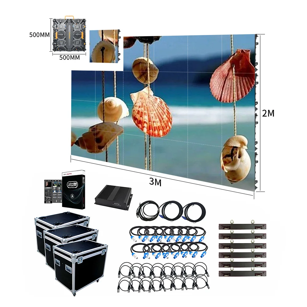
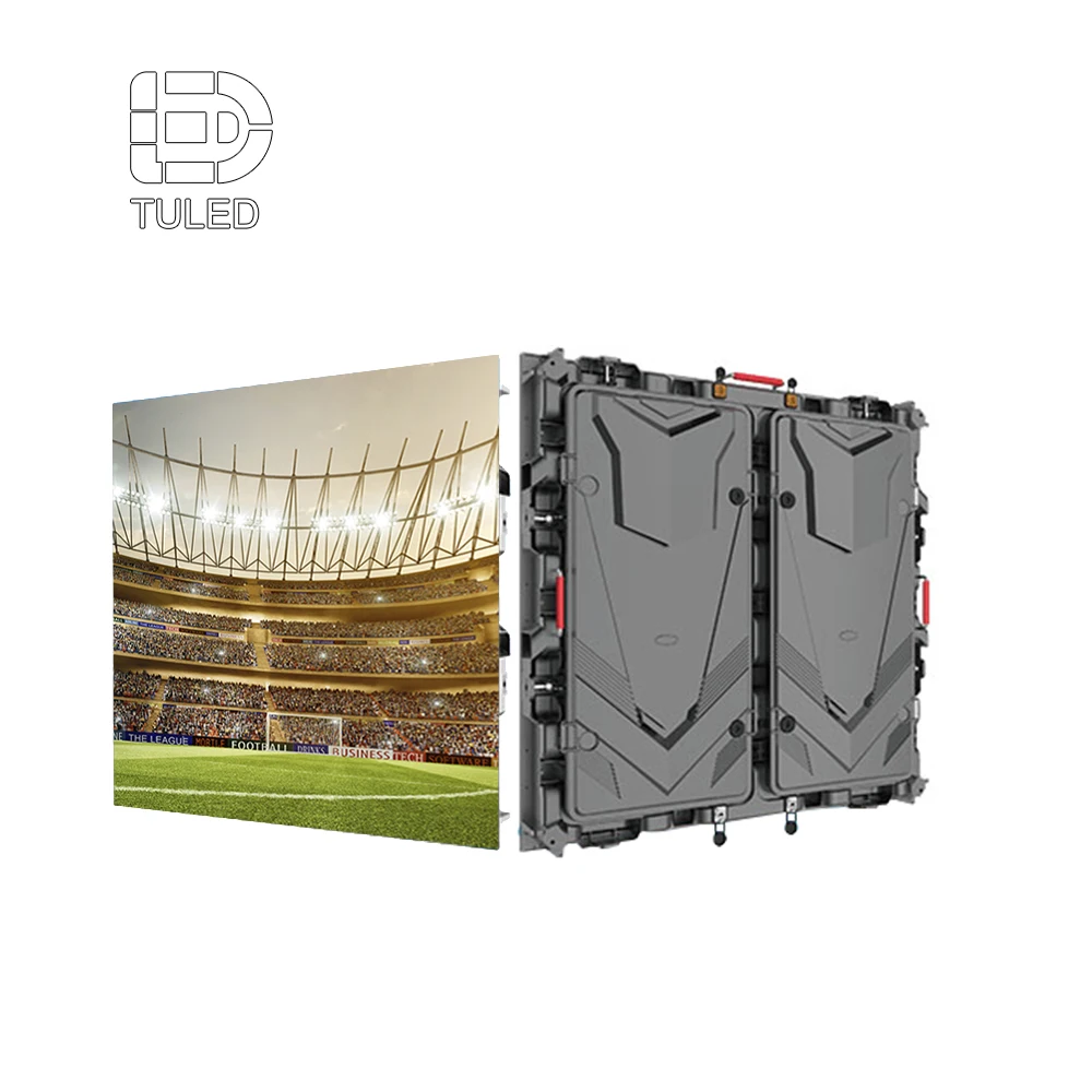
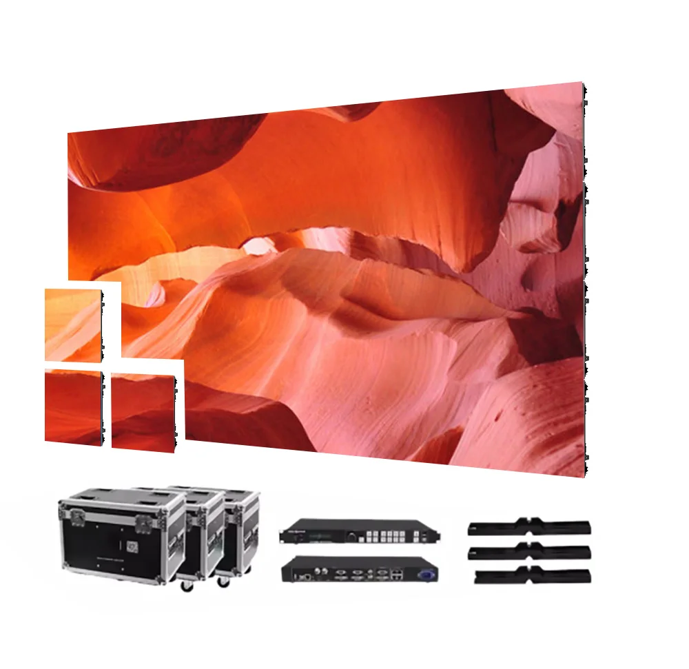
A product image cannot replace an electrical drawing, but real cabinet hardware shows where power entry, rear service space, metalwork, cable paths, and structural interfaces physically sit. Equipment selection and electrical planning should therefore develop together rather than in separate files.

Start the electrical review from the actual cabinet and installation path
The cabinet format affects cable entry, rear access, branch wiring, service space, and the physical relationship to the support structure. The final electrical package should match the selected display configuration rather than rely on a generic outdoor schematic.
Review Outdoor LED Cabinet OptionsMap the Grounding Relationship Across Distribution, Structure and Control Equipment
Grounding discussions often become vague because several conductive systems appear on one project. The incoming supply has its own earthing arrangement. The LED distribution cabinet has protective conductors and exposed conductive parts. The screen may sit on a large steel frame, while the control processor and network switch operate from another location. One ground symbol on a drawing cannot explain that full relationship.
A more useful drawing begins at the power source and follows the protective path to every relevant node. At the same time, it shows the structural and control interfaces that could otherwise remain hidden in separate mechanical, AV, or network drawings. The final arrangement still needs confirmation under the applicable local electrical design by qualified personnel.
Start upstream before discussing the screen frame
The grounding review should begin with the source that feeds the LED installation. In practice, the site survey should record the main supply origin, the board that feeds the LED circuit, the phase arrangement, the local distribution position, the feeder route, and the protective conductor path. These fields give the electrical team enough context to understand how the screen connects to the wider installation.
Two screens with identical cabinets can have very different grounding questions. For example, one display may sit a few metres from a building distribution board. Another may stand beside a road and receive power through a long underground feeder. The hardware can look the same, yet the electrical boundaries, route exposure, maintenance access, and surge coordination questions are different.
Treat the local LED distribution cabinet as a major node
The local distribution cabinet is often the point where one incoming feeder becomes several screen circuits. It is the natural place to document isolation, protective devices, protective-conductor termination, outgoing branches, SPD positions, monitoring contacts, and maintenance access. A drawing that shows only breakers but not the earthing relationship leaves an important part of the system undefined.
Physical layout matters as well. A protection device may appear correct on a schematic while its field connection takes an unnecessarily indirect path. Accordingly, the single-line diagram and the cabinet layout should be reviewed together. No universal conductor length, cross-section, or termination method should be copied into every project; those details belong to the approved electrical design and device instructions.
Show the screen structure as part of the electrical interface
Large outdoor installations can include cabinet frames, support steel, columns, rear maintenance platforms, ladders, railings, façade brackets, access doors, and other conductive parts. However, structural drawings often treat those items only as mechanical components. The electrical review should identify which exposed conductive parts are relevant to the approved bonding concept and where connection points are expected.
The display manufacturer can define connection interfaces on supplied equipment. Meanwhile, the site electrical design determines how those interfaces relate to the building or freestanding structure. This division of responsibility is important because site earthing arrangements, structural systems, lightning protection, and local rules vary. A factory diagram should clarify interfaces without pretending to replace local engineering.
Control equipment belongs on the same grounding map
Control hardware can sit far from the screen. For example, the processor may operate inside a control room while receiving equipment sits inside outdoor cabinets. A network switch may be powered from one distribution board while the screen power comes from another. Consequently, chassis connections, power earth, shielded interfaces, and conductive data links deserve the same attention as the LED feeder.
This is also where fibre becomes useful as an architectural decision. Fibre can remove a conductive data path between distant equipment groups. However, local switches, converters, processors, power supplies, and metal structures still need their own electrical protection. Fibre reduces one path; it does not make grounding and surge planning unnecessary.
A practical grounding-map test
If the project drawing cannot trace the protective relationship from the supply origin to the local distribution cabinet, screen metalwork, structural interface, and remote control equipment, the grounding package is not complete enough for handover review. The missing answer should be resolved in engineering rather than left for field interpretation.
| Element | Record in the project file | Reason for the record |
|---|---|---|
| Incoming supply | Source, board, electrical arrangement, route start | Establishes the upstream context for the LED feeder. |
| LED distribution cabinet | Location, incoming feed, outgoing groups, isolation | Defines the main screen-side electrical node. |
| Protective conductor | Route and approved termination points | Makes the protective path traceable on drawings and on site. |
| Screen cabinet metalwork | Relevant protective or bonding interface | Avoids undefined exposed conductive sections. |
| Support steel | Frame, columns, service structures, interface points | Connects structural drawings with the electrical protection concept. |
| Control equipment | Processor, switch, converter, power source, chassis context | Prevents remote electronics from being omitted from the grounding map. |
| External data links | Copper or fibre, route, entry point, connected equipment | Shows whether another conductive path crosses an outdoor boundary. |
| Inspection points | Accessible test or verification locations | Makes final checking and future maintenance practical. |
Plan SPD Protection by Electrical Boundary and Lightning Zone
A surge protective device, or SPD, is used within an electrical protection system to limit transient overvoltage. However, the phrase “surge protection included” is too vague for a project submittal. The useful information is where the device sits, which circuit it protects, what exists upstream, what equipment sits downstream, and how the proposed stage fits the site electrical design.
Type 1, Type 2, and Type 3 terminology appears in common low-voltage SPD practice, yet exact application depends on the governing electrical framework and the approved system design. These labels are useful coordination fields, not a universal recipe for every outdoor screen. Final selection, ratings, associated protection, conductor arrangement, and installation method require project confirmation. For a concise overview of the three stages, see Schneider Electric’s SPD overview.
Start with the protection boundary, not the device label
Before an SPD type appears on the bill of materials, the project team should identify the relevant electrical boundaries. For example, power may enter a building at the main service, leave through an outdoor feeder, pass through a local LED distribution cabinet, and finally reach several groups of screen power supplies. Each transition creates a different coordination question.
The same logic applies to a freestanding structure. A long feeder may connect the site distribution system to a cabinet located at the sign base. From there, shorter branch circuits feed the LED cabinets. Instead of treating the local SPD as a standalone feature, engineering should check its relationship to upstream protection, the feeder, local earthing conditions, and the connected electronic loads.
Use Type 1, Type 2 and Type 3 as a discussion framework
In a layered protection discussion, Type 1 is commonly associated with higher-energy exposure at an installation origin or relevant incoming boundary. Type 2 is commonly discussed at downstream distribution locations. Type 3 is commonly considered closer to sensitive loads as part of coordinated protection. However, the exact arrangement should come from the project electrical design and the selected device documentation.
For an LED installation, this framework is useful because it turns one vague “SPD” line into several design questions. Does the site already have upstream protection? Is the LED feeder long or external? Where is the local distribution point? Are control electronics located far from that cabinet? Does a copper communication line create another entry path? The answers determine what needs engineering attention.
| SPD stage | Useful project question | Do not assume without confirmation |
|---|---|---|
| Type 1 | Is a high-energy incoming boundary or lightning-related interface part of the site design? | That every outdoor screen automatically requires the same device or rating. |
| Type 2 | Which distribution point needs coordinated transient protection for downstream circuits? | That the local LED cabinet can be specified without reviewing upstream protection. |
| Type 3 | Do sensitive downstream electronics need an additional coordinated protection stage? | That point-of-use protection can replace upstream coordination. |
Lightning protection zones make boundaries easier to discuss
A lightning protection zone, often shortened to LPZ, is a way to divide an installation into areas with different lightning electromagnetic environments. In project planning, the concept helps identify where cables cross boundaries and where bonding, shielding, isolation, or surge protection may need coordination. The LED screen itself cannot define the complete zone plan because the surrounding structure and site protection system matter.
For example, a signal cable can begin inside a building, leave that environment, cross an outdoor route, and enter a remote sign cabinet. Similarly, a power feeder can pass from the main distribution system to a separate structure. Those transitions deserve explicit review. If the site uses an external lightning protection system, the LED installation should be coordinated with that system by the qualified project professionals. The current IEC 62305-4:2024 reference covers surge protection measures for electrical and electronic systems exposed to lightning electromagnetic impulse.
SPD installation quality depends on more than the nameplate
A protection device can only be assessed in context. Accordingly, the submittal should identify the protected circuit, installation position, system voltage basis, upstream protective arrangement, downstream load group, grounding connection concept, status indication, replacement access, and reference drawing. Those fields allow the local electrical team to review the actual installation rather than a catalogue description.
Connection geometry also deserves attention. Long or indirect connections can change the real behaviour of a transient protection path. However, this article does not prescribe a universal connection length or conductor size. The selected SPD instructions, approved electrical design, short-circuit conditions, local requirements, and site layout should determine those details.
Weak submittal wording
“Lightning protection included.”
“Industrial surge protector.”
“Anti-thunder device in cabinet.”
Useful submittal fields
Location and protected circuit.
Protection stage and upstream relationship.
Device reference, indication, service access, and approval status.
Build an SPD schedule that can survive handover
An SPD schedule should remain understandable after commissioning. For that reason, each device entry can include cabinet or panel name, circuit reference, physical location, protection stage, manufacturer and model once selected, system basis, upstream device reference, downstream equipment group, status indication method, alarm contact if used, replacement method, and drawing reference.
The schedule should also record who confirms the final selection. The display engineering team can define LED-side loads, cabinet interfaces, and proposed locations. Meanwhile, the local qualified electrical professional should confirm site-specific ratings, coordination, installation method, earthing arrangement, applicable requirements, and final acceptance criteria.
Long Power and Signal Runs Need Their Own Lightning-Induced Surge Review
Cable length is normally discussed for voltage drop, signal integrity, cost, and installation labour. However, an outdoor route also creates a longer physical path through the site environment. When conductors cross exposed areas, separate structures, façades, roofs, poles, or long underground routes, lightning-related electromagnetic effects and potential differences become part of the electrical discussion.
The practical response is not to assign a universal maximum cable length. Instead, the route should be mapped accurately. Engineering can then review entry points, exit points, conductive loops, parallel services, shielded interfaces, grounding conditions, and protection at the relevant boundaries. This approach also avoids treating every long cable as the same risk.
- Building-mounted screen: confirm the feeder origin, façade exit, cabinet entry and structural bonding interface.
- Remote roadside billboard: prioritise the long feeder, local distribution cabinet, support steel, and protection at both ends.
- Rooftop display: coordinate the screen with the building’s lightning-protection and roof-level cable boundaries.
- Control link between structures: compare external copper protection with a fibre route, including converter power at both ends.
Record route geometry, not only total metres
A feeder that remains inside one building does not create the same review as a feeder that leaves the building and travels to a freestanding billboard. Likewise, an overhead section differs from a buried route, and a façade route differs from a cable inside a metal service corridor. Accordingly, the site survey should describe where the cable runs, not just how long it is.
Useful route fields include total length, outdoor length, underground sections, overhead sections, building exit point, sign entry point, intermediate cabinets, nearby conductive services, shared containment, structural crossings, and any change in the site protection environment. A route sketch often reveals more than a single number on the RFQ.
Power feeders deserve review at both ends
When a long feeder connects two distant electrical nodes, the source end and the load end both matter. The source side may contain the main distribution protection. The remote side may contain a local LED distribution cabinet and another grounding interface. As a result, one end cannot be designed in isolation from the other.
The project should document the upstream protection, feeder construction, route, local distribution point, connected load groups, and proposed surge protection. However, the final device arrangement depends on the approved electrical system. This is especially important for roadside and remote advertising structures where the display is physically separated from the building supplying it.
Copper signal routes are electrical paths too
LED control networks often include Ethernet, serial links, monitoring cables, sensor wiring, synchronization lines, or other low-voltage interfaces. A copper cable between two equipment groups creates a conductive path even though it carries data rather than mains power. Consequently, external copper should appear on the same protection review as the power feeder.
The project record should identify the interface type, cable route, shielding method where applicable, equipment at both ends, network speed requirement, external boundary crossings, and any interface-specific surge protection proposal. A power SPD cannot simply substitute for a data-line protective device. The protection method has to suit the signal interface and the approved network design.
Use fibre when electrical separation is part of the design goal
Optical fibre can remove the metallic data conductor between distant points. For that reason, it can simplify the electrical relationship between a building control room and a remote outdoor display. Fibre is particularly useful when a long external copper link would otherwise connect separate equipment locations.
Still, fibre should not be described as a complete lightning solution. Media converters, network switches, processors, local power supplies, and screen cabinets remain connected to electrical power. In addition, cable constructions with metallic armour or strength members may create separate bonding questions. The final cable type and treatment should follow the complete project design.
Avoid unnecessary loop area in power and signal layouts
Large conductor loops can increase electromagnetic coupling. Accordingly, cable routes should be organised rather than spread casually across a large steel structure. Related conductors should follow the approved routing concept, and unnecessary separation that creates large loops should be avoided where the electrical design permits.
This point applies inside the display as well as outside it. A tidy cabinet does not guarantee a tidy system if branch circuits and return paths wander across a large billboard frame. Therefore, internal routing drawings should be reviewed together with external feeder and signal routes. The aim is controlled geometry and traceable paths, not a universal layout copied from another project.
Outdoor sign structures make cable boundaries easier to see
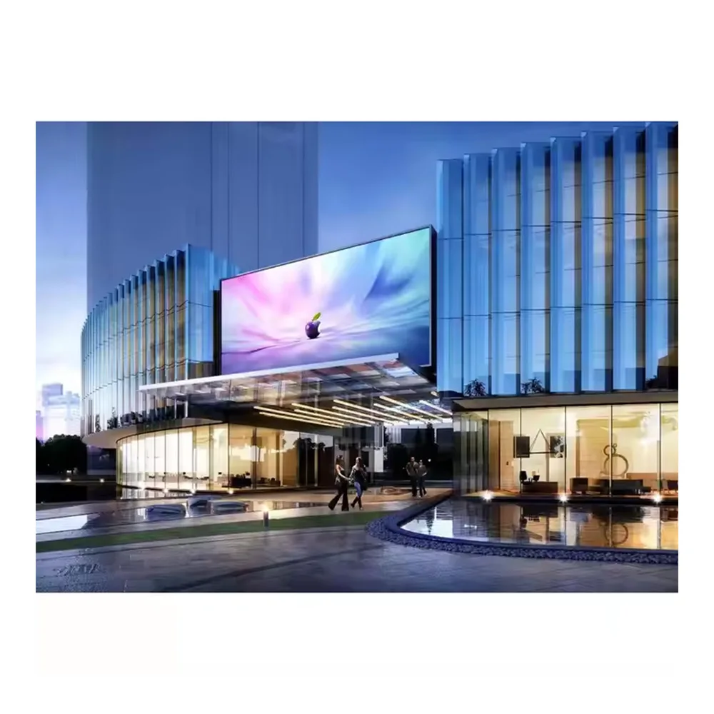
A freestanding sign often has an obvious physical boundary. Power leaves a building or site distribution point, crosses an outdoor route, and enters the sign base or local cabinet. Data may follow copper or fibre. For that reason, a roadside billboard proposal should include electrical interface documentation rather than only screen hardware.
Pole-mounted, roadside, rooftop, and exterior commercial signs create similar coordination questions. A visually simple sign can still have a long feeder, separate support steel, a remote control path, a local isolator, and an external lightning-protection interface. Clear drawings reduce the number of assumptions transferred to site work.

Treat the sign, feeder, structure and control link as one project system
An LED Sign Board project should record the power origin, local distribution point, screen structure, signal method, external cable route, and grounding conditions before final electrical engineering. This creates a better handover boundary between the display package and site work.
Review LED Sign Board Options| Route field | Record | Why it changes the review |
|---|---|---|
| Total feeder length | Source to local LED distribution point | Provides context for voltage, routing and surge coordination work. |
| Outdoor route length | Distance outside protected indoor areas | Shows how much of the route crosses an external environment. |
| Installation method | Underground, overhead, façade, tray, conduit, mixed | Different physical routes create different interfaces and service conditions. |
| Copper data route | Interface, route, shield, equipment at both ends | Identifies a conductive communication path that may cross protection boundaries. |
| Fibre route | Cable construction, converters, power at each end | Separates the optical link from the electrical equipment that supports it. |
| Boundary crossings | Building exit, outdoor entry, remote cabinet, structural transition | Creates clear locations for protection and bonding coordination. |
Build Grounding and Electrical Checks Into Project Handover
A display that powers on is not automatically ready for electrical sign-off. Commissioning should preserve evidence of the installed protection system, including the actual feeder route, protective-conductor path, bonding interfaces, SPD locations, control-network topology, inspection results, and locally required records. This information becomes especially valuable when equipment is serviced or modified later.
The handover package should separate observed results from acceptance criteria. The local electrical design defines which measurements are required and which limits apply. Accordingly, the LED project checklist should provide fields for the approved criterion, measured result, drawing reference, date, and sign-off party rather than inventing a universal resistance value or pass/fail threshold.
Update drawings to the installed condition
Field conditions often change the original plan. A distribution cabinet may move, a cable route may shift, or a signal link may change from copper to fibre. As a result, the final handover drawing should describe the installed system rather than the tender concept. An outdated drawing makes future fault investigation slower and can hide protection changes.
At minimum, the as-built set should keep the single-line power diagram, grounding and bonding relationships, feeder route, cable entry positions, control topology, SPD schedule, and relevant structural interfaces aligned. If the project has a defined lightning-zone plan, those boundaries should also match the final installation.
Keep local electrical test records with the LED project file
The qualified local electrical team should complete the inspections and measurements required for the approved project. Because the sequence and acceptance criteria vary with the electrical system, jurisdiction, installation type, and project specification, the handover form should record the test name, approved criterion, instrument or method reference where required, measured result, location, date, and responsible sign-off. This preserves traceability without inventing a universal acceptance limit.
Use a responsibility split that prevents missing scope
The LED engineering package should identify loads, cabinet interfaces, power entry positions, control topology, supplied distribution equipment, proposed SPD positions, relevant metalwork interfaces, and service access. These are equipment-side facts needed by the wider project team.
By contrast, the local qualified professional should confirm the site earthing arrangement, protective-conductor design, bonding method, SPD selection and coordination, lightning-protection interface, cable installation rules, overcurrent protection, isolation, test requirements, and final compliance. The integrator or contractor then needs to ensure the installed work matches both sets of information.
LED engineering package
- Power-load and cabinet-group information
- Power and signal entry positions
- Control-system topology
- Supplied distribution-cabinet scope
- Proposed SPD positions where included
- Equipment-side grounding or bonding interfaces
Local electrical confirmation
- Applicable local electrical requirements
- Earthing and protective-conductor design
- Bonding of relevant conductive parts
- SPD type, rating and coordination
- Lightning-protection system interface
- Inspection, testing and final acceptance
Copyable outdoor LED electrical handover checklist
The following fields can be copied into an RFQ, technical submittal, site survey, commissioning form, or final sign-off sheet. In practice, the list works best when each line has a document reference or responsible party beside it.
Site and supply
- Installation location recorded
- Main power source identified
- LED feeder origin identified
- Feeder route and length documented
- Outdoor route sections identified
- Intermediate distribution points identified
Grounding and bonding
- Site earthing arrangement confirmed locally
- Protective-conductor route shown
- Distribution-cabinet interface shown
- Screen metalwork relationship shown
- Support structure reviewed
- Accessible verification points identified
Surge protection
- Existing upstream protection documented
- Local LED cabinet protection reviewed
- SPD stage and protected circuit recorded
- Coordination reviewed by the electrical team
- Status indication and replacement access checked
- Final selection approved for the project
Lightning-zone review
- Existing lightning protection status recorded
- Relevant protection boundaries identified
- Building-to-outdoor transitions reviewed
- Display entry boundary reviewed
- Copper data crossings reviewed
- Local professional confirmation recorded
Signal network
- Control-room location recorded
- Processor and switch locations recorded
- External copper links identified
- Fibre sections and converters identified
- Shielding method documented where applicable
- Interface protection requirement reviewed
Final records
- As-built single-line diagram included
- Grounding relationship drawing included
- Cable route and network topology included
- SPD schedule included
- Required local test records included
- Final labels and maintenance access checked
Use a sign-off table that records evidence instead of assumptions
| Check item | Project field | Handover evidence |
|---|---|---|
| Protective-conductor continuity | Approved criterion / method | Result, location, date, sign-off |
| Bonding of relevant metalwork | Drawing and local requirement | Inspection record and as-built reference |
| SPD installation | Approved device and installation detail | Panel reference, status, photo or inspection entry |
| External cable route | Approved route and protection concept | As-built route drawing |
| Signal boundary | Copper/fibre interface and protection decision | Network topology and installed interface record |
| Local electrical inspection | Applicable project requirements | Signed inspection or test documentation |
FAQ
Why can an outdoor LED screen’s IP rating not replace grounding and surge protection?
An enclosure rating addresses ingress at the equipment boundary. Grounding, bonding, protective conductors, transient overvoltage, external cable paths, and lightning-related interfaces are separate electrical questions. A suitable enclosure can still be connected to an incomplete grounding system or an uncoordinated surge-protection arrangement.
How should the grounding relationship between the distribution cabinet, screen structure and control equipment be organised?
The map should begin at the incoming supply and trace the protective relationship through the LED distribution cabinet to relevant cabinet metalwork and support structures. Remote control equipment and conductive communication links should appear on the same system drawing. The final earthing and bonding arrangement requires confirmation by qualified local electrical personnel.
Which electrical-zone information should be confirmed before SPD positions are final?
The review should identify the supply origin, main and local distribution points, building-to-outdoor transitions, external feeder route, display entry point, sensitive electronics, conductive signal crossings, existing upstream protection, and any lightning-protection-zone boundaries defined by the project. Those fields provide the context needed for device selection and coordination.
Why do long power and signal cables increase lightning-induced surge concerns?
A long external conductor crosses more of the site environment and can connect equipment at different electrical locations. Route geometry, boundary crossings, electromagnetic coupling, grounding conditions, and protection at both ends therefore deserve review. Copper signal links need the same attention because they create conductive paths between electronic equipment.
What should be confirmed with local electrical personnel before project handover?
The final review should cover the site earthing arrangement, protective-conductor design, bonding of relevant conductive parts, overcurrent protection, isolation, SPD selection and coordination, lightning-protection interface, cable installation, inspection access, required tests, acceptance criteria, labels, and as-built records. Local qualified professionals should determine the applicable rules and project-specific limits.
Submit the site electrical conditions before final protection configuration
A useful engineering review starts with the installation city or region, screen mounting type, incoming power arrangement, main distribution position, local LED cabinet position, feeder length, underground or overhead routing, site earthing information, existing lightning-protection information, control-room location, copper or fibre signal route, and available single-line or site drawings.
With those fields available, the outdoor LED screen grounding and surge protection review can focus on the LED-side distribution interface, proposed SPD locations, cable-entry arrangement, control topology, and equipment-side grounding points. The final earthing method, protection ratings, lightning coordination, and compliance checks should then be confirmed by the qualified local electrical team.
Submit Electrical Project Details