EN
EN

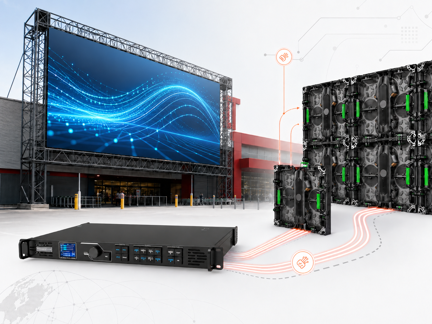
A custom LED screen signal architecture has to do more than carry an image from a source to a display. Once a route crosses a ceiling, riser, technical room, or another floor, cable length, conversion points, rack access, patching, and backup coverage all affect whether the system can be commissioned and maintained reliably.
For a Custom LED Screen project, the plan should define where copper stops, where fiber begins, where processing and sending equipment sit, and which failures a secondary path can survive. The most serviceable architecture usually has clear equipment boundaries, accessible racks, documented patching, and few hidden active devices.
Why a long LED run becomes two different signal problems
These layers are related but not interchangeable. Define the start and end of each link before selecting copper, fiber, transmitters, receivers, or spare paths.
Copper or Fiber? Start With the Installed Route
HDMI and SDI should not be judged by connector type alone. The useful question is whether the selected cable, signal format, route, patching, and receiving equipment can support the complete installed path. Distance planning therefore begins with the cable route, not a general limit copied from another project.
A floor plan may show a short distance between the control room and display, while the installed cable travels through trays, ceilings, risers, service corridors, rack entries, and slack loops. A straight-line measurement can substantially underestimate the working path.
The floor plan rarely shows the real cable length
Before selecting transport, the route record should show each physical transition. Service loops and patching belong in the estimate rather than being treated as zero-length details.
- Source equipment room or source rack
- Video processor position
- Sending equipment position
- Cable tray and ceiling route
- Vertical riser transitions
- Intermediate patch panels
- Display-side rack or control enclosure
- Service slack at both ends
Keep copper where it makes service easier
Short electrical links can keep a rack simple. For example, a nearby source and processor may not need optical conversion when the selected cable supports the required signal. Similarly, a short connection between devices in one technical room may be easier to maintain as a direct copper path.
The objective is not to replace every cable with fiber. The architecture should identify the point where a local equipment connection becomes a building-scale transport problem. Once that boundary is clear, the system is easier to document and troubleshoot.
Use fiber when the route becomes a building problem
Long optical transport is often easier to manage when the signal must cross floors, distant equipment rooms, or large venue spaces. At the same time, fiber can separate equipment zones electrically and reduce dependence on a long copper path. Still, optical transport needs its own engineering checks.
Fiber type, transceiver compatibility, connector format, route condition, patch count, and available strands all need project confirmation. Likewise, an existing building fiber panel should not automatically be treated as usable infrastructure. The actual strand path and condition still need verification.
| Transport Approach | Where It Usually Fits | What Needs Confirmation |
|---|---|---|
| Passive HDMI | Short local device connections where the complete cable path is already validated. | Signal format, selected cable, connector condition, and installed distance. |
| Active / Optical HDMI | Longer point-to-point source links where one defined path is preferred. | Direction, power requirements, termination, service access, and cable specification. |
| SDI over Coax | Professional video transport where coax infrastructure and patching are practical. | Signal rate, cable construction, connector quality, patch count, and route length. |
| Fiber Backbone | Long routes, risers, distant racks, route separation, and building-scale distribution. | Fiber type, transceivers, connector format, strand assignment, loss budget, and patching. |
| Mixed Copper + Fiber | Large systems where local rack links remain simple and long routes move to optical transport. | The exact conversion boundary and responsibility for every active stage. |
A quick way to choose the transport
This is a planning shortcut, not a universal distance rule. Final approval must follow the selected equipment specifications and an installed-path test.
A mixed architecture is often easier to maintain than an all-or-nothing approach. For instance, several short device links can remain inside one rack while a single optical backbone carries the long-distance segment. In this arrangement, the transition point becomes an obvious test boundary.
Several powered extenders placed above ceilings create the opposite result. If the image disappears, each hidden power supply becomes another suspect. Keeping conversion points in known technical locations makes the route easier to test and repair.
How the same choice changes by project
Meeting room or showroom: when the player and processor share an accessible rack near the screen, validated copper links may be the simplest option.
Shopping-mall atrium: a control room on another floor turns the riser and building pathway into the main design issue, so local copper plus a documented fiber backbone is often easier to service.
Command center or public information wall: continuity matters more, so the proposal may need separate transport paths, duplicated conversion hardware, and a tested recovery method rather than one unverified spare cable.
Where Should the Processor and Control Rack Go?
Equipment location changes both signal length and maintenance effort, so rack placement should not be decided only by available space. A technically short cable route can still be a poor design when the critical hardware becomes difficult to reach.
Three positions commonly compete for control hardware: the source room, a central technical room, and a rack near the display. Each creates a different transport boundary, which is why equipment placement and cable planning must be reviewed together.
Keep processing close to an accessible operating point when practical
A processor often benefits from an accessible technical position because signal checks and configuration work happen there. Meanwhile, local source connections can remain short when playback equipment occupies the same room. The long transport segment can then begin at a clearly documented point.
However, accessibility alone does not settle the decision. If the processor location creates several additional conversion stages before the display, another topology may be cleaner. The complete path should be reviewed rather than optimizing one device in isolation.
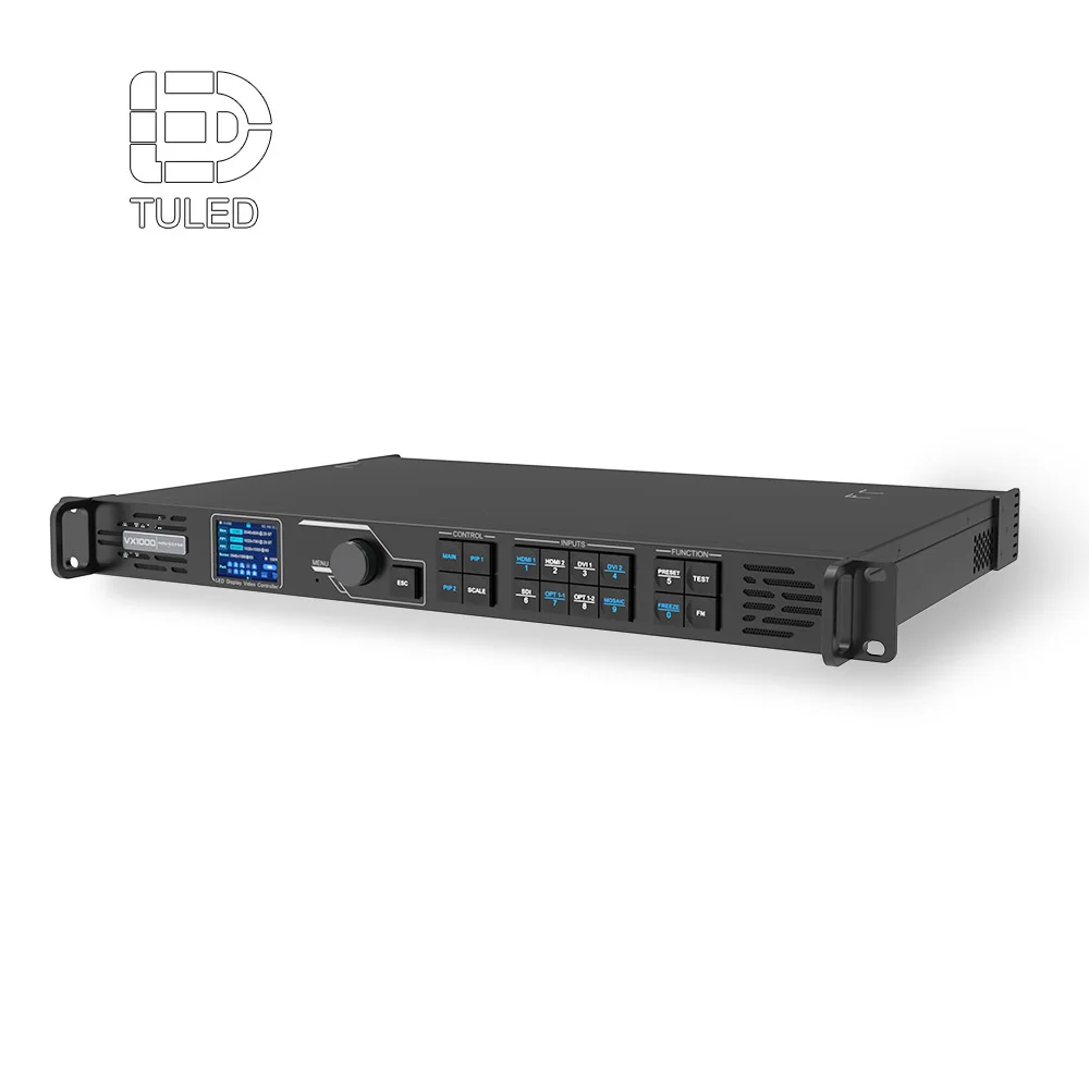
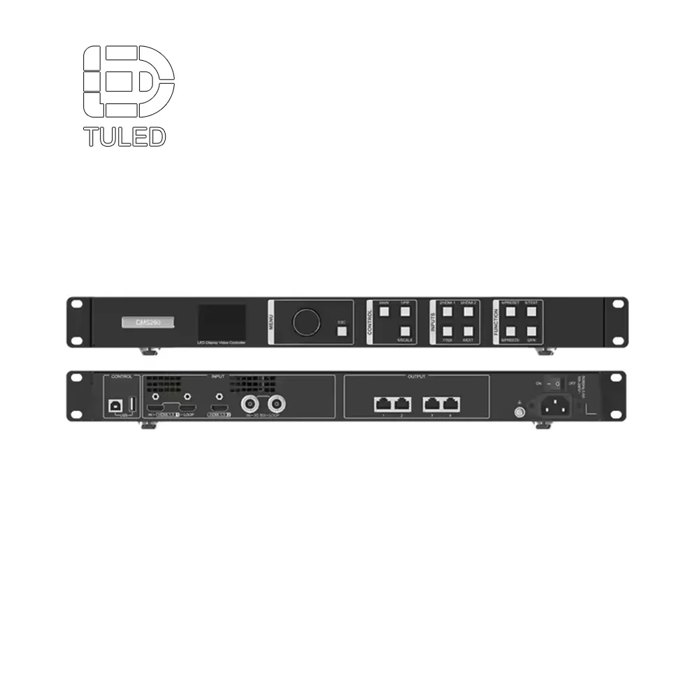
VX1000 control hardware reference from the site product range. Confirm total LED pixel load, source format, output-port plan, backup requirement, and any optical conversion hardware against the approved topology before ordering.
Check VX1000 CapabilitiesSending equipment can remain with the processor or move closer to the display
One architecture keeps processing and sending equipment together in a control rack. In that case, the long-distance backbone begins after that equipment cluster. Another architecture carries the source signal toward the display and places more control hardware near the screen.
Neither arrangement is automatically correct. Instead, the stronger option normally has fewer fragile long links, fewer hidden converters, and a clearer service boundary. Stable power and practical ventilation also matter at the selected rack location.
Rack location decision questions
- Which connection becomes the long-distance backbone?
- Which active devices sit at each end of that backbone?
- Which rack provides stable power and suitable ventilation?
- Which equipment may need regular configuration or physical access?
- Can optical patching remain visible and labeled?
- Can a failed unit be replaced without opening architectural finishes?
- Can the rack be reached while the display remains in operation?
Avoid inaccessible active devices in the middle of the route
A mid-route converter can solve a drawing problem while creating a maintenance problem. For example, an active device hidden above a finished ceiling requires power, identification, and physical access. Later, a simple signal fault may require opening architectural finishes before testing can begin.
A cleaner design keeps active devices at known rack boundaries whenever possible. In turn, passive cable infrastructure carries the signal between those locations. This arrangement gives the integration team predictable test points at both ends.
Separate source handling from display-side distribution
Source handling and LED cabinet distribution are related but distinct parts of the system. As a result, separating these functions can make the topology easier to understand. Media sources and processing may remain in one technical zone, while receiving and cabinet-level distribution remain closer to the display.
Choose video processing, sending equipment, receiving hardware, and related LED control accessories after the architecture is clear. Otherwise, the project risks buying compatible-looking devices that create an awkward signal chain.
Do not judge a rack by empty space alone. Power affects shared-failure risk; cooling affects processors and converters; visible fiber patching creates useful test points; and door, rear-panel, and operating-hour access affect recovery time. Local electrical, grounding, fire, and building requirements still need coordination with qualified professionals.
What Does a Backup Path Actually Protect?
A second cable does not automatically create useful redundancy. If both paths share one conduit, transmitter, rack, and power source, several failures can still interrupt both routes. Backup design should begin by defining the failure that the secondary path is expected to survive.
Different projects need different resilience levels. A mission-critical information wall may justify device duplication and physical route separation, while a decorative installation may only need a tested spare cable and a documented manual recovery procedure. Set the protection level before adding hardware.
Start with a failure boundary, not a “redundant” label
A useful review asks what happens when one component disappears. For example, a single fiber strand, optical transmitter, processor output, rack power feed, or physical cable route may fail. The drawing should then show whether another path exists around that exact failure.
This approach makes redundancy measurable. In addition, it prevents a proposal from appearing more resilient than the physical installation. Each backup feature can be connected to one defined risk.
Failures worth testing during architecture review
- One source output becomes unavailable.
- One processor output becomes unavailable.
- One sending device fails.
- One optical transmitter or receiver fails.
- One backbone fiber is interrupted.
- One rack loses power.
- One patch lead is disconnected or damaged.
- One physical pathway becomes unavailable.
Two routes should not share every dependency
Two fibers in the same conduit may protect against one damaged strand. However, they do not protect against damage to the conduit itself. Likewise, two transmitters in the same rack may still depend on one power source or one upstream processor.
Partial redundancy is not necessarily wrong. Instead, its scope should be described accurately. A project can state that dual optical links protect the transport segment while the processor remains a common dependency.
Physical route diversity must exist outside the signal diagram
A primary line and a backup line can appear separated on a schematic while sharing the same tray in the building. In that case, the diagram implies more protection than the installation provides. Therefore, construction routing should be checked together with the logical signal flow.
For higher-resilience systems, the review should identify each riser, conduit, tray, and display entry point. Complete separation may not be practical everywhere. Still, the shared portions should be visible so the remaining risk is understood.
Primary and Backup Path Logic
Common start if required
Path A endpoint
Defined route
Display-side rack
Final common stage
Defined divergence point
If equipment redundancy is required
Separate where practical
Recovery endpoint
Must be documented
Backup links also need a defined operating method
A spare cable is useful only when the recovery action is known. Depending on the agreed system, recovery may use an automatic changeover, a manual patch, a preconnected standby route, or a documented spare-device procedure. The architecture should state which method applies.
A simple manual strategy can be suitable when recovery time is not critical. Conversely, another project may require a faster changeover. The important point is that commissioning should test the intended behavior instead of assuming that installed backup hardware guarantees recovery.
| Failure Event | Possible Protection | Shared Dependency to Check |
|---|---|---|
| One fiber fails | Secondary optical path | Same conduit, patch panel, or receiver |
| One transmitter fails | Secondary transmit stage | Same power source or processor output |
| Rack power fails | Project-specific alternate power strategy | Common upstream electrical dependency |
| Route is damaged | Physically diverse pathway | Shared riser, tray, or building entry |
| Processor fails | Spare or alternate processing strategy | Same source and downstream control path |
How Multi-Floor Projects Change the Plan
Once a route crosses floors, it starts behaving like building infrastructure rather than a single AV cable. The signal may pass through a main control room, riser, floor distribution room, patch field, and display rack before it reaches the screen. Every handoff adds another place where a wrong port or unclear label can stop commissioning.
Define the role of those locations before counting strands or placing converters. A room that only passes fiber through does not need the same hardware as a point where the signal branches or changes format.
Not every technical room needs active equipment
Passive termination is often easier to maintain because it adds no power supply, heat, or firmware. Active optical conversion belongs where the topology actually requires it and where a technician can reach it. In either case, port numbers, strand assignments, and destinations need to stay consistent across the drawings.
Typical infrastructure zones
- Source or media equipment room
- Central AV or technical control room
- Building distribution room
- Floor telecom or technical room
- Intermediate passive patch location
- Display control rack
- Rear display service area
Document fiber, spare strands and patch boundaries as one system
The word “fiber” is not a complete specification. A usable proposal identifies the optical medium, connector format, strand count, endpoints, patch count, and loss budget required by the selected transport equipment. Existing building fiber is valuable only after its route, condition, termination, and compatibility have been verified.
Extra capacity reduces future disruption only when it is traceable. Give both ends of every primary, backup, and spare strand the same reference, patch-panel location, destination, status, and owner. The schedule also needs to expose route sections shared by the main and backup paths.
A patch panel is a controlled test boundary between cable segments, not just cable organization. Show each panel in the signal flow and cable schedule, but avoid unnecessary patching that creates extra connections without a clear service or coordination benefit.
| Patch Field | Information to Record | Reason |
|---|---|---|
| Rack ID | Room and rack reference | Finds the physical endpoint quickly |
| Panel / Port | Panel identifier and port number | Creates a repeatable patch location |
| Destination | Opposite rack or panel | Removes ambiguity during service |
| Role | Primary, backup, or spare | Connects physical patching to topology |
| Status | Installed, tested, reserved, unavailable | Supports handover and later changes |
Keep the names stable. A backbone labeled FO-01 on one drawing cannot quietly become “Fiber A” on another schedule. The same rule applies to racks, processors, patch panels, sending equipment, and display IDs. As-built documents use the final installed names, not obsolete concept labels.
Remember that fiber is still a physical cable. Construction affects bending, pulling, crushing, environmental exposure, rack entry, and service-loop storage. Selecting an optical transport method does not remove those installation limits.
Assign responsibility at every handoff
Large buildings often divide the work between several technical disciplines. One contractor may install pathways, while another terminates the fiber and an AV integrator connects the LED control equipment. Without a clear handoff, testing responsibilities can disappear between scopes.
A simple responsibility schedule prevents that gap and makes quotation comparisons clearer because each technical party can see which work remains outside the equipment supply.
Multi-floor handoff checklist
- Pathway installation responsibility
- Backbone fiber installation responsibility
- Fiber termination responsibility
- Fiber test-report responsibility
- Patch-panel labeling responsibility
- Optical transmitter and receiver installation
- LED control hardware installation
- Rack power and ventilation scope
- Primary path commissioning
- Backup path commissioning
- Final as-built documentation
What an Integrator Needs to See on the Signal Diagram
A useful Signal Flow Diagram lets an integrator understand the route without a long verbal explanation. A single line from “processor” to “LED wall” hides the exact information that becomes important on a long run: where the equipment sits, where the signal changes format, and which part belongs to the main or backup path.
Can a technician trace the route from one page?
Give every source and display a stable identifier, physical location, and relevant interface. When the transport method changes, put the active converter on the drawing as well. An extender hidden from the schematic becomes a hidden failure point during service.
The diagram does not need to reproduce every meeting-room switching detail. Its job is to show the complete long-distance path—from the named source and processor, through each conversion and backbone segment, to the sending stage and final LED display.
Example long-run signal flow structure
Add the physical and operational fields behind each connection
Two boxes may sit next to each other on a diagram while being separated by several floors. Give every major node a stable ID plus its room and rack, such as PROC-01 in CR-01 and RX-01 in LED-RACK-01. On each long link, state the transport method and reference the cable schedule for connectors, patch ports, strands, route length, and installation status.
Do not rely on color alone to identify redundancy. Use labels such as PRIMARY, BACKUP, PATH A, and PATH B, and show where the routes separate and rejoin. Keep every common processor, receiver, rack, pathway, and relevant power dependency visible so the drawing does not overstate independence.
Record surveyed or planned distances on the links that determine transport technology. Update those values when construction changes the route, then transfer the final installed lengths and identifiers to the as-built cable schedule.
Signal Flow Diagram field checklist
| Field | Required Information | Engineering Purpose |
|---|---|---|
| Display ID | Unique display name or code | Prevents confusion on multi-screen sites |
| Source ID | Source name and physical location | Creates a traceable starting point |
| Source Interface | Confirmed output connection | Defines the first signal layer |
| Processor | ID, room, and rack | Shows processing position |
| Conversion Device | Electrical-to-optical or other active stage | Exposes powered failure points |
| Main Transport | Path A cable or optical method | Defines normal operation |
| Backup Transport | Path B method and endpoints | Defines resilience scope |
| Route Length | Planned or surveyed length | Supports transport validation |
| Fiber Type | Project-confirmed optical medium | Supports compatible optical selection |
| Strand Assignment | Pair or strand schedule reference | Supports installation and recovery |
| Patch Panel | Rack, panel, and port | Creates a defined test boundary |
| Sending Stage | ID and location | Defines the LED control boundary |
| Rack Power Note | Relevant shared dependency | Checks redundancy claims |
| Test Requirement | Normal and backup path checks | Makes commissioning measurable |
| Drawing Revision | Revision and date | Prevents outdated installation work |
From a Good Idea to a Quote That Can Be Built
Signal architecture should survive the handoff from design to procurement. Otherwise, a carefully planned topology may become a simple equipment list during quotation. The technical request should therefore include the real source-to-display environment.
Screen size and resolution alone do not describe a long-run signal project. Instead, the package should record control-room location, available fiber, rack positions, floor crossings, route length, and required resilience. These fields allow equipment selection to follow the infrastructure.
Information to attach to the technical inquiry
- Number and location of LED displays
- Total LED pixel load, screen resolution, and planned output-port allocation
- Source location
- Source resolution, frame rate, color depth, interface, and HDCP requirement when relevant
- Control-room or processor location
- Proposed display control rack location
- Longest planned transmission route
- Number of floors or technical zones crossed
- Existing fiber type, connector, strand count, route, patch count, and test report when available
- Required optical distance and loss budget for the selected transmitter and receiver pair
- Existing copper or coax infrastructure
- Primary path requirement
- Backup path requirement
- Required physical route separation
- Known patch-panel locations
- Maintenance access limitations
- Known building or electrical coordination requirements
A useful quote explains the chain, not just the boxes
A parts list cannot show whether the devices form a maintainable signal chain. A useful technical response shows where processing occurs, where optical transport begins, where the display-side control boundary sits, and which dependencies remain common to the primary and backup paths.
This approach makes technical proposals easier to review. For example, an optical transmitter line item becomes meaningful only when the matching route, endpoint, fiber plan, and power location are known. Otherwise, the equipment exists without an architecture around it.
Connector type is only one compatibility check. Review source resolution, frame rate, color depth, HDCP behavior where relevant, processor input limits, total LED pixel load, output-port allocation, transport devices, fiber type, connector, strand count, patch loss, and the final receiving chain together.
Existing building cables need site verification before the design depends on them. The same rule applies to spare fiber: identify it at both ends, test it, and include it in the schedule so the backup path can be traced during commissioning.
Test one boundary at a time
Layered testing reduces the size of a troubleshooting problem. At first, local source-to-processor operation can be confirmed. Next, the long transport link can be tested before the final display-side distribution is added.
Once the normal path works, test the backup route independently and then demonstrate the complete failure-recovery procedure. This sequence creates known working boundaries throughout commissioning.
- Confirm local source-to-processor operation.
- Confirm processor output at the transport boundary.
- Test the primary long-distance path.
- Test the backup long-distance path.
- Confirm the display-side sending and receiving chain.
- Run the complete normal signal path.
- Interrupt the primary route and follow the agreed recovery procedure.
- Record final rack, port, cable, and strand assignments.
- Update the signal flow to match the installed system.
- Issue the final as-built cable and fiber schedule.
Continuity is not recovery. A backup cable can test correctly while the operating procedure remains unclear. Create the failure that the backup route is meant to survive and observe the real recovery method. Manual labels need to work under time pressure; automatic changeover needs to be tested with the selected equipment.
Finish with the installed facts. Racks move, patch ports change, and strand assignments shift during construction. The as-built package records the final equipment locations, cable IDs, fiber assignments, patch ports, primary and backup designations, and tested recovery method. Months later, those records may save more troubleshooting time than any decorative detail on the original drawing.
Questions Buyers Usually Ask
When should a copper signal path change to fiber?
There is no single distance that fits every HDMI or SDI installation. Instead, the decision should consider signal format, selected cable, installed route, connector count, equipment capability, and service conditions. Fiber becomes more attractive when the route crosses large areas, floors, risers, distant technical rooms, or physically separated backup pathways.
Does a second fiber create full redundancy?
Not by itself. Two fibers in one conduit can protect against one damaged strand but not against conduit damage, shared rack power, or a common processor. Describe redundancy by the failures it actually covers rather than by a broad label.
What information should a Signal Flow Diagram provide to an integrator?
At minimum, it should identify sources, processors, sending equipment, conversion devices, transport links, display-side equipment, physical locations, and primary or backup roles. For longer routes, it should also reference path length, fiber assignments, patch panels, and cable schedules so installation and commissioning remain traceable.
What to Decide Before Requesting a Final System Proposal
Long-distance LED transport works best when cable choice, equipment position, redundancy, and building pathways are treated as one system. Copper can remain around local equipment where it keeps the design simple; fiber can carry the building-scale segment when distance, routing, infrastructure handoff, or resilience justifies the change.
Three final actions make the design easier to review and quote:
- Record the real route. Confirm source location, control-room position, display position, rack locations, floor transitions, patch points, and longest transmission distance.
- Define the failure coverage. State whether the secondary path must protect one cable, one converter, one rack, one active device, or an entire physical pathway.
- Prepare the handoff fields. Confirm source interfaces, processor position, fiber availability, strand assignment, patching, primary path, backup path, and final Signal Flow Diagram responsibility.
Send the information that changes the design
For a custom LED screen signal architecture review, submit the source list and formats, total LED pixel load, control-room or processor location, display location, rack positions, longest installed route, floors crossed, existing fiber details, and required backup coverage. If available, attach the floor plan or current signal diagram plus fiber test results. These details provide the basis for deciding where copper should end, where fiber should begin, which equipment is compatible, and where each control device should sit.
Submit Signal Architecture Details