EN
EN

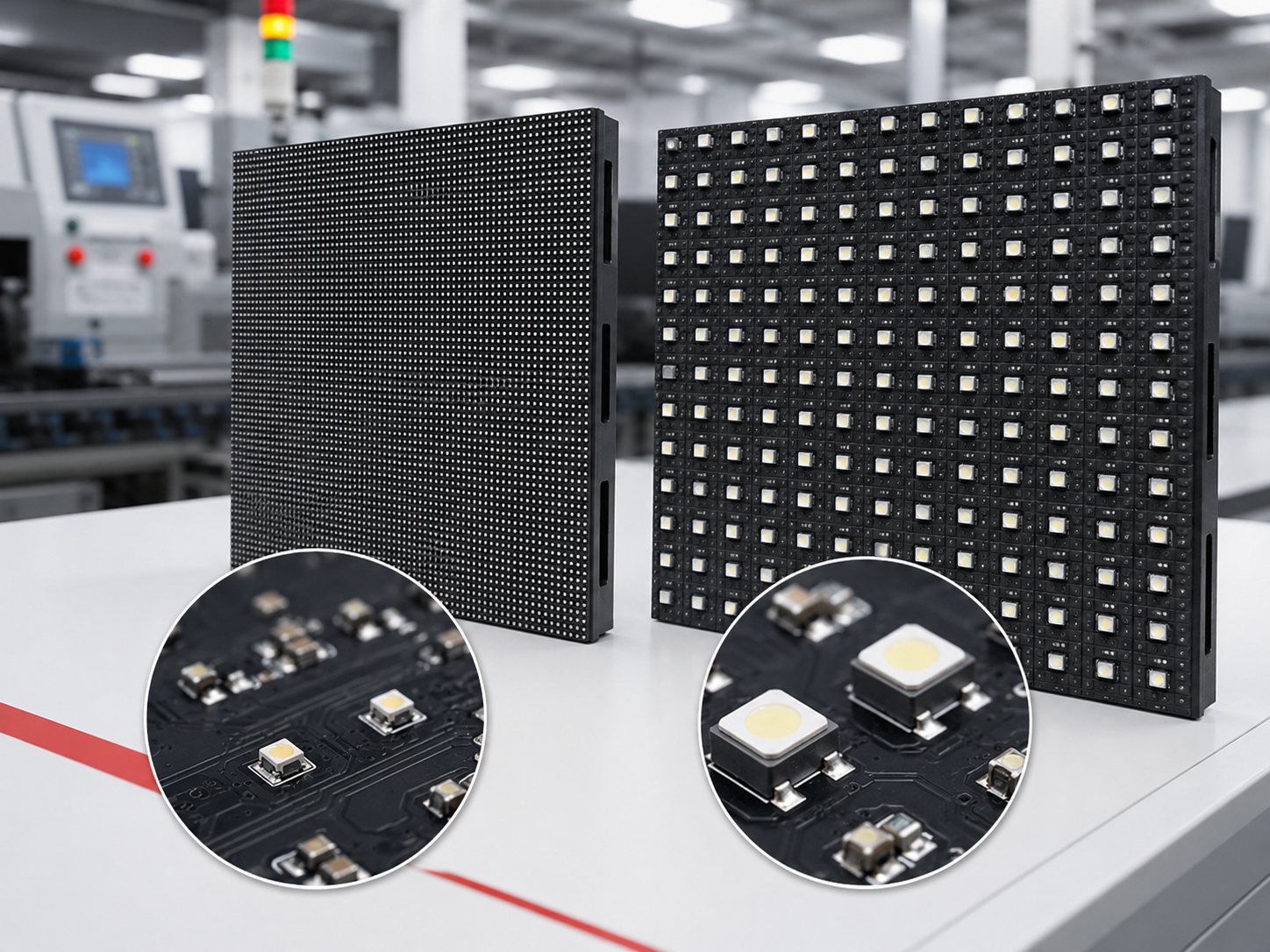
The practical answer to the SMD 1010 vs SMD 2121 LED display question is not simply “smaller is better” or “larger is brighter.” SMD1010 is usually the stronger direction for P1.x and selected P2 indoor screens where viewers sit close, text is small and high native resolution must fit within limited wall space. SMD2121 is often more practical for P2.5, P3 and related indoor platforms where readable output, mature production, easier repair and controlled total cost matter more than extreme pixel density.
P2 is the main overlap zone. A meeting-room screen, retail wall or camera-facing display can favor either package depending on ambient light, black-surface quality, grayscale performance, operating brightness and the complete module design. Compare finished LED display modules under the same settings before approving a package.
Choose the direction in less than a minute
- P1.25–P1.8, close viewing, small text or dense dashboards: start with a verified SMD1010 or other compact fine-pitch platform.
- P2 meeting rooms, bright interiors or camera-facing walls: do not decide from the package code. Compare complete modules side by side.
- P2.5–P3, moderate viewing distance and cost-sensitive indoor use: an SMD2121-based platform is often the more practical starting point.
- Any project with long operating hours or future spare-module needs: approve the exact package, chip, PCB, driver and calibration configuration, not only “1010” or “2121.”
SMD 1010 vs SMD 2121 LED Display: Key Differences
Use this table to narrow the options. The exact package series and finished-module sample still decide the final result.
| Decision factor | SMD1010 direction | SMD2121 direction |
|---|---|---|
| Nominal package class | Compact body in the 1.0 mm class | Larger body in the 2.1 mm class |
| Typical indoor pitch direction | P1.x and selected P2 platforms | P2, P2.5, P3 and related platforms |
| Main buying reason | Fit more pixels into limited wall space and support close-view detail | Balance readable output, mature production, serviceability and cost |
| Visual advantage to verify | Fine text, low gray, dense resolution and dark surface between pixels | Useful brightness, legibility, viewing stability and practical black level |
| Main risk | Tighter placement, soldering, cabinet-flatness and repair tolerances | Paying for a mature package but accepting weak chips, glossy surfaces or poor calibration |
| Best evidence | Close-view sample, low-gray test, macro assembly review and seam check | Warm-state brightness, off-state reflection, viewing-angle, repair and batch comparison |
| Usually better for | Control rooms, boardrooms, command centers and close-view information walls | Retail walls, transport information, exhibitions and standard commercial indoor displays |
Simple recommendation: choose SMD1010 when the project genuinely needs closer viewing or more pixels in a restricted area. Choose SMD2121 when a wider pitch already meets the visual requirement and the project gains more from stable production, easier service and cost control. For P2, insist on a side-by-side module test.
What the SMD Package Numbers Actually Mean
SMD means surface-mounted device. In a conventional full-color module, one package normally contains red, green and blue chips and mounts directly on the PCB. The numbers 1010 and 2121 identify the nominal package-body class. They do not tell you the pixel pitch, screen resolution or final image quality.
Pixel pitch is the center-to-center distance between neighboring pixels. A compact package can fit inside a smaller pixel cell, but the PCB still needs space for pads, traces, solder mask and placement tolerance. This is why two P2 modules can use different package strategies and still have the same nominal pixel pitch.
The code does not tell you what is inside the package
Two packages with the same four-digit code can produce different results. Ask for the exact component series and confirm:
- RGB chip source, grade and approved substitutions
- Brightness, wavelength or chromaticity bin control
- Black package material, surface gloss and optical cavity
- Lead-frame structure, terminal finish and recommended PCB land pattern
- Encapsulation material, moisture handling and reflow requirements
- Lot traceability for production and spare modules
The module design matters just as much. Driver IC, scan mode, PCB copper, current settings, power distribution and calibration can make a strong package look poor or make a standard package perform well. The guide on how an LED display module works explains how these parts affect the complete screen.
Choose SMD1010 When Close Viewing and Dense Resolution Matter
SMD1010 becomes valuable when the screen needs a fine pixel pitch and the project can actually use the extra resolution. It is not an automatic premium upgrade. The smaller package is worth considering when viewers sit close, content contains fine detail or the available wall area is too limited for a wider pitch.
Projects that commonly benefit from the compact package
Control rooms, command centers, boardrooms, broadcast backgrounds and high-resolution information walls often need P1.x or selected P2 platforms. Operators may read small labels for hours. Meeting participants may sit close enough to notice pixel texture. A broadcast camera can expose low-gray steps or module boundaries that bright promotional footage hides.
A compact black package can also leave more dark PCB or mask area around each pixel. That may improve the unpowered appearance and perceived black level under controlled indoor lighting. The benefit only holds when the package face, PCB finish and mask remain dark and low-gloss.
What you gain—and what you must control
The main gain is density. More pixels can fit into a given screen size, which helps fine text, line graphics, maps and dashboards. The trade-off is tighter manufacturing tolerance. Small placement errors, package rotation, uneven solder paste or PCB warping occupy a larger share of the visible pixel grid.
Repair also requires more care because neighboring pixels sit close to the work area. Uncontrolled heat or tool pressure can damage more than one package. Cabinet flatness and module alignment deserve equal attention; a small depth difference can interrupt a dense image even when each module passes its own bench test.
Choose the SMD1010 direction when most of these statements are true
- The project requires a verified P1.x or selected P2 platform.
- The normal viewing position is close enough to reveal pixel structure.
- Small text, thin lines or dense data are part of the real content.
- The required native resolution must fit within limited wall dimensions.
- Low-gray quality and dark-surface appearance carry high weight.
- The supplier can show stable placement, soldering and cabinet alignment.
- Production and spare modules will use traceable component lots and calibration records.
When the application cannot use the extra density, a compact package may add cost and process sensitivity without producing a visible benefit. In that case, spend the budget on better calibration, cabinet precision, control hardware or spare-module planning instead.

Choose SMD2121 When Practical Indoor Performance Matters More Than Maximum Density
SMD2121 is often used on indoor platforms where the pixel cell has more room and extreme density is not the main buying reason. The larger package can fit mature P2, P2.5 and P3 production lines, making it a practical direction for commercial displays that need clear content, predictable service and balanced project cost.
Where the larger package usually makes sense
Retail video walls, exhibition displays, transport information boards, school or corporate halls and general commercial indoor screens often begin at a moderate viewing distance. Large text, branding, video and public information remain readable without pushing the pitch into the finest range.
A mature SMD2121 platform may also be easier to inspect and repair at component level. Existing stencil, placement and reflow settings can reduce production uncertainty when the supplier has real experience with the module. Maturity is an advantage only when the process is controlled; it does not excuse weak materials, poor soldering or uncontrolled substitutions.
Do not assume every SMD2121 module is brighter or cheaper
Brightness depends on the RGB chips, optical cavity, current setting, scan mode, PCB and thermal path. Cost depends on the full module and screen. Pixel pitch changes the number of LEDs, driver channels and solder joints per square meter, so package price alone is not a useful purchasing comparison.
Ask for the target operating brightness, not only the maximum value shown in a sales sheet. A strong peak number has little value if the screen develops heat, color drift or weak low-gray performance at the level used every day.
Choose the SMD2121 direction when most of these statements are true
- P2.5 or P3 already provides enough resolution at the normal viewing distance.
- The content is mainly large text, video, branding or public information.
- The project values predictable production, repair access and cost balance.
- Useful operating brightness matters more than the darkest possible pixel surface.
- The supplier can confirm the exact indoor package and module BOM.
- Future replacement modules can be supplied with controlled materials and calibration data.
A practical standard-module direction
For P2.5 and related indoor projects, review a standard 320×160 mm module platform and confirm whether the selected configuration uses SMD2121, SMD1515 or another approved package. The product label and BOM should match the sample you approve.
Review 320×160 indoor module options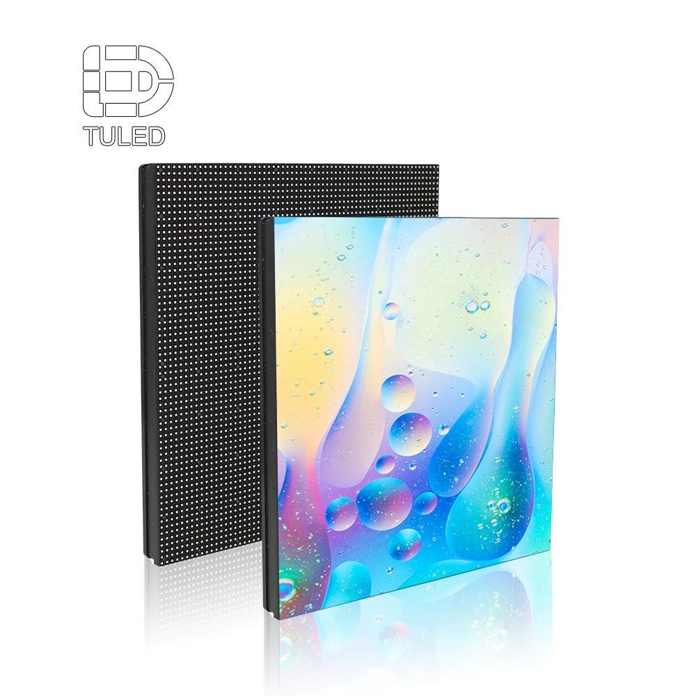
P2 remains a comparison, not a fixed rule
A P2 boardroom may favor a compact black package because viewers sit close and dark slides are common. A bright retail interior may favor a larger-package platform with stronger usable output. A transport information screen may value long operating hours and quick replacement more than subtle black-level differences.
Run both modules with the same video source, color temperature, grayscale mode and target luminance. Check off-state black, low gray, full white, fine text, side-view color, power and temperature after warm-up. The winner is the module that performs better in the actual room, not the one with the more impressive package name.
Which Package Direction Fits Your Project?
These project examples translate the technical differences into a buying decision. They are starting points, not substitutes for a sample.
Control room or command center
Start with: SMD1010 or another verified fine-pitch package.
Operators sit close and read dense information for long periods. Prioritize native resolution, small-text clarity, low-gray smoothness, cabinet seams and replacement-module matching. Do not pay for a smaller pitch until the screen dimensions and source resolution show that the extra pixels are useful.
Boardroom or executive meeting room
Start with: SMD1010 for P1.x; compare both directions at P2.
Presentation text, spreadsheets and dark slides can reveal uneven gray and module boundaries. Check the normal seat distance, not the closest person who may briefly walk past the wall. Compare the unpowered black surface under the actual room lights.
Retail wall, lobby or exhibition display
Start with: project-dependent P2, or SMD2121 direction at P2.5–P3.
Ambient light, reflections and viewing distance often matter more than ultra-fine detail. Check readable output near glass or strong ceiling lights, but avoid selecting the module only by maximum brightness. Review dark scenes and the unpowered screen because the display remains part of the interior when it is off.
Transport information or public data screen
Start with: SMD2121 direction when P2.5 or P3 meets the legibility requirement.
Text stability, long operating hours, replacement speed and consistent spare modules usually matter more than extreme black level. Test the real font size and line spacing from the farthest important viewing point. Confirm that replacement modules and receiving-card configuration files will remain available.
Broadcast studio or camera-facing background
Start with: compact fine-pitch direction, then test the complete module and control system.
No package can guarantee clean camera performance. Refresh settings, scan mode, grayscale, processor settings, camera shutter and shooting angle all interact. Run the actual camera and intended content before approval. A visually attractive phone video is not enough evidence.
Still unsure? If your project falls between two directions, send the screen size, viewing distance, content type and operating environment before requesting a quotation. That information is more useful than asking for “the best LED package.”
What Changes the Finished Screen Beyond Package Size?
Native resolution must match the screen and content
A smaller pitch increases pixel density, driver channels and solder joints per square meter. The extra pixels help only when the wall dimensions, source resolution and content can use them. Calculate the real horizontal and vertical resolution before choosing the package. A P1.x screen that only plays low-resolution promotional video may add complexity without adding visible value.
Black level depends on the complete front surface
A smaller package can expose more dark area between pixels, but package gloss, mask color, PCB finish and room lighting decide whether that advantage survives in the finished module. Compare powered and unpowered samples under the actual lighting. Side light often reveals reflections that a straight-on product photo hides.
Brightness should be judged at the daily setting
Maximum brightness is not the same as useful operating brightness. Ask how the screen performs at the level used every day. After warm-up, check luminance, white point, color uniformity and temperature. This prevents a high headline number from hiding thermal drift or weak low-gray behavior.
Viewing angle is an optical design issue
Internal chip position, optical cavity, encapsulation and mask geometry affect how red, green and blue light spreads. A module may stay bright from the side but develop color shift. Another may hold color balance while losing luminance. Test white, gray and primary colors from the real seating and mounting positions.
Heat belongs to the module and cabinet
A fine-pitch layout places more heat sources in a smaller area, but package size alone does not determine temperature. PCB copper, driver placement, solder joints, current settings, power distribution and cabinet ventilation create the real thermal path. Run samples until temperature stabilizes, then compare optical performance again. The CIE guidance for LED measurement explains why measurement conditions must remain controlled.
What to Confirm Before You Approve a Module or Request a Final Quote
You do not need to turn the purchase into a laboratory project. Focus on the checks that prevent the most expensive mistakes: choosing the wrong pitch, approving an unknown sample, accepting uncontrolled substitutions or ordering spare modules that will not match later.
Give the supplier enough project information
A useful recommendation should be based on:
- Active screen width and height
- Normal and closest viewing distances
- Required source or native resolution
- Main content, smallest text and graphic detail
- Ambient light, nearby windows and expected operating brightness
- Daily operating hours and camera use
- Front or rear service method and cabinet limits
- Required delivery schedule, spare-module plan and installation location
Ask for six pieces of approval evidence
- Exact package and module BOM: package model, chip source, PCB revision, driver IC and scan mode.
- Traceable sample label: the sample should be linked to the materials and calibration records used during testing.
- Real-content demonstration: fine text, low gray, full white and the content that the screen will actually show.
- Warm-state comparison: brightness, color and temperature after the module has reached stable operation.
- Physical inspection: package alignment, surface shade, solder condition, module flatness and cabinet seams.
- Change-control commitment: approval should be required before the supplier changes the package, chip, PCB, driver or calibration method.
Warning signs during supplier comparison
- The quotation lists only “SMD1010” or “SMD2121” without the exact package series.
- The sample looks good, but no one can confirm its PCB, driver or LED lot.
- Brightness is compared at different settings or before the modules warm up.
- Only bright promotional video is shown; no text, low gray or unpowered surface is reviewed.
- The supplier can replace materials without written approval.
- Spare modules are offered without a plan for matching lots, calibration data and future availability.
The buying rule that prevents most problems
Approve a complete, traceable module configuration. A package code can narrow the options, but the purchase record should lock the package series, chips, PCB, driver, scan mode, calibration method and agreed sample appearance.
Common SMD1010 and SMD2121 Buying Mistakes
Choosing the smallest package without checking viewing distance
A finer pitch can look impressive in a specification sheet, but it may not improve the installed image when viewers stand farther away or the content lacks fine detail. Calculate the required resolution first.
Assuming SMD2121 automatically means high brightness and low cost
The package code cannot confirm either result. Compare finished modules at the same output and include the full screen cost, calibration, cabinet precision, repair and spare-module strategy.
Approving a demo without approving the materials
A good-looking sample has little purchasing value when its chip, package lot, PCB and driver are unknown. The production order may arrive with a different configuration and a different visual result.
Ignoring the unpowered screen
Lobby and meeting-room displays remain visible when switched off. Uneven package shade, glossy surfaces and module-to-module color differences can reduce the finish of the entire interior.
Leaving spare modules until after installation
Later lots may use different materials or show a different black surface and white point. Order and record the spare-module strategy with the original project whenever possible.
Frequently Asked Questions
What do 1010 and 2121 mean in SMD LEDs?
They normally identify the nominal package-body class. SMD1010 is in the 1.0 mm class and SMD2121 is in the 2.1 mm class. Exact dimensions, terminals and internal construction can vary, so the component drawing and package model still need confirmation.
Is SMD1010 always better for fine-pitch LED displays?
No. Its compact size can support tighter pixel layouts and more dark surface between pixels, but the module still needs precise placement, soldering, good chips, thermal control and calibration. Choose it when the installed project can use the extra density.
When is SMD2121 the more practical choice?
It is often practical for P2.5, P3 and related indoor platforms where moderate viewing distance, readable output, mature assembly, repair access and cost balance matter. Confirm the exact package on the approved BOM rather than assuming every product at those pitches uses SMD2121.
Which package should I choose for P2?
P2 is a direct-comparison pitch. Test complete modules at the same brightness, source settings and warm operating condition. Meeting rooms may favor black level and low gray; bright retail areas may favor usable output and reflection control.
Can the package code confirm viewing angle, brightness or lifespan?
No. Viewing angle depends on optical design. Brightness depends on chips, current, scan mode and thermal design. Long-term reliability depends on materials, soldering, PCB design, temperature and production control. Use the package code as a selection clue, not a guarantee.
What should I send before requesting a recommendation?
Send the screen size, viewing distance, content type, smallest text, ambient light, operating hours, service method, camera requirements and expected project schedule. These details allow the package and pixel pitch to be matched to the real installation.
Final Recommendation: Choose the Screen Requirement Before the Package
Choose SMD1010 when close viewing, fine text and dense resolution create a visible project benefit. Choose SMD2121 when P2.5 or P3 already meets the viewing requirement and the project benefits more from a mature indoor platform, easier service and controlled cost. At P2, compare complete modules and let the installed conditions decide.
Do not approve a production order from a four-digit package code alone. Lock the exact package series, RGB chips, PCB, driver IC, scan mode and calibration process after the sample passes. This protects the initial screen and makes future spare-module matching easier.
Get a project-specific package and pixel-pitch recommendation
Send the active screen size, normal viewing distance, content type, ambient light, operating hours, service direction and camera requirements. The technical team can then narrow the pitch, compare suitable module platforms and explain whether an SMD1010 or SMD2121 direction creates real value for the project.