EN
EN

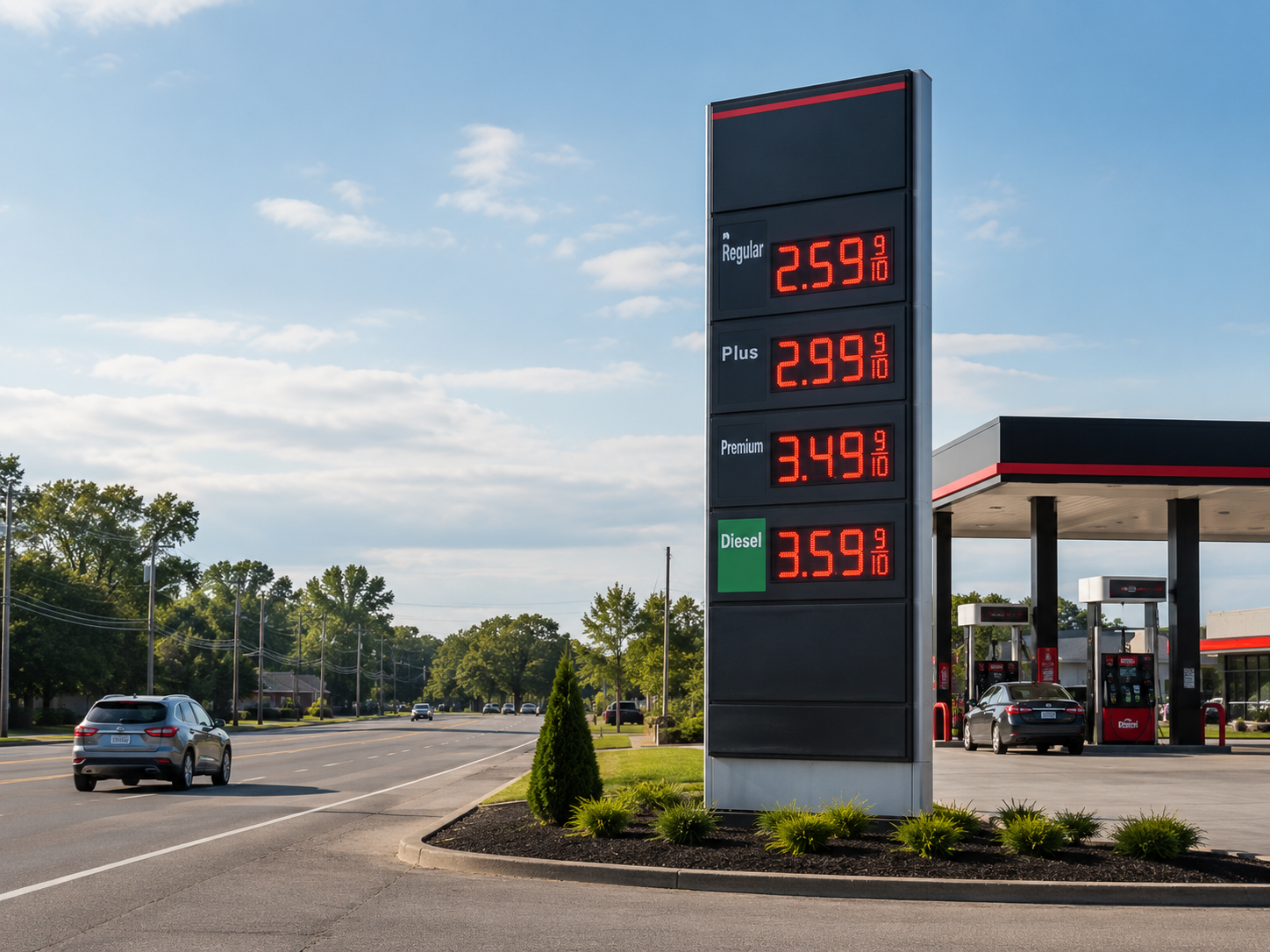
A gas station LED price sign has only a few seconds to communicate. A vehicle approaches, several price rows enter view, the figures are checked, and attention returns to traffic. That brief moment depends on much more than a bright LED module. Character height, road speed, sunlight, night glare, rain, remote updates, electrical protection, and maintenance access all shape the result. This guide turns those technical subjects into practical project decisions that can be checked on the road, compared during procurement, and verified after installation.
Roadside test
Can the complete price be recognized before the vehicle reaches the entrance?
Night test
Do the numerals remain sharp without turning into a bright halo above wet pavement?
Update test
Can one approved change reach the correct row and return a clear confirmation?
Service test
Can a module, controller, sensor, or power unit be reached without unsafe improvisation?
01 · Start with the roadside experience
Why a Gas Station LED Price Sign Is Not a Standard Outdoor Advertising Screen
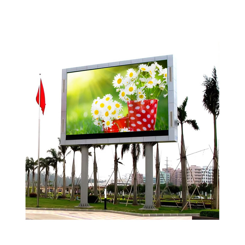
A conventional outdoor advertising screen can use movement, full-color graphics, changing layouts, and long messages. A roadside fuel display works under a tighter visual limit. It normally presents only a few numbers, yet every number must remain recognizable during a moving glance.
Therefore, the design priority changes. Resolution is useful only when it supports a clean numeral shape. Brightness is valuable only when the surrounding black area stays dark enough to create contrast. Remote control matters only when a price change reaches the intended row without uncertainty.
In practice, the finished display should feel simple from the road. Fuel names remain easy to locate. Price rows form a clear vertical rhythm. Decimal positions stay consistent, while decorative elements never compete with the figures.
A realistic five-second approach
Consider a late-afternoon approach on a busy urban road. The windscreen carries a light film of dust. One lane contains a delivery vehicle, while another vehicle blocks the lower part of the pylon. At the same time, low sunlight falls across the sign face.
The pylon may remain visible for twenty seconds, but the useful reading period can be much shorter. The figures become clear only after an obstruction passes. Then the road curves, the viewing angle changes, and attention must return to traffic.
During that brief period, the display should not require interpretation. The first row should not look attached to the second. A decimal should not disappear into a reflection. Likewise, narrow strokes should not fade when the sign moves toward a side angle.
As a result, a strong design creates calm rather than spectacle. It makes the information feel dependable. That quiet confidence has practical value because the display forms part of the site’s daily operating environment, not a temporary advertising campaign.
A useful three-second test
Show the proposed layout for three seconds, then remove it. If the full prices and row order cannot be repeated accurately, adding more graphics will not solve the problem. Larger characters, cleaner spacing, stronger contrast, or fewer distractions usually provide a better result.
Daily price changes shape the control system
A showroom demonstration often happens indoors and close to the cabinet. Real operation may happen during a busy shift, after heavy rain, or late at night. One row may need an immediate change while the remaining rows must stay untouched.
At that moment, the control interface should look familiar. The digital row order should match the physical row order. Each face of a double-sided pylon should carry a clear identity, and the latest successful update should be easy to confirm.
An effective process usually follows five plain steps: enter, verify, approve, send, and confirm. That sequence may feel unremarkable, which is useful. A predictable workflow reduces hesitation and helps prevent one incorrect digit from reaching the roadside display.
Communication failure also needs an agreed response. The sign may retain the last confirmed price, enter a defined warning state, or follow another approved rule. The chosen behavior should be documented before installation rather than decided during the first network interruption.
Fixed numeric fields or a flexible LED matrix
Dedicated numeric modules can provide a direct and simple presentation. They may suit projects that require fixed digit positions and limited content. By contrast, a full LED matrix can provide greater layout freedom, brand colors, labels, arrows, or future content changes.
Neither method is automatically superior. The choice affects pixel geometry, spare parts, software, power zones, maintenance access, and future changes. Accordingly, the quotation brief should state whether the sign needs numbers only or a more flexible display area.
A highly flexible module may become unnecessary when the display will always show four static fuel rows. Conversely, a fixed numeric design may become restrictive when brand rules require changing labels or multilingual information. The expected operating life should guide the decision.
02 · Readability from a moving vehicle
Matching Character Height, Road Speed and Useful Viewing Distance
Character height should begin with the traffic approach, not the empty space inside an existing cabinet. A numeral can look generous during a close inspection yet feel small when viewed through a windscreen from a moving lane.
Three distances help clarify the project. Detection distance marks where the pylon first becomes noticeable. Recognition distance marks where the fuel rows and numbers become understandable. Decision distance marks the last comfortable point before a lane choice or site entrance.
Those distances are rarely identical. A tall branded structure may be detected early, while its actual prices remain unreadable until much later. For that reason, the site survey should record the first reliable reading point rather than the first sight of the pylon.
Survey the journey rather than one fixed position
A practical survey starts before the sign becomes visible. The route should follow the lane used by the intended approach. During that journey, the survey records speed, lane offset, sign angle, clear sightline length, and the point where all required rows become readable.
Obstructions often change throughout the day. Parked trucks, delivery vehicles, canopy columns, trees, traffic signals, bridge rails, and neighboring signs may block part of the view. Seasonal landscaping can also hide lower rows after the initial survey.
Meanwhile, the opposite traffic direction deserves a separate review. One side of a double-faced pylon may receive low afternoon sun, while the other appears through a sharper horizontal angle. Identical hardware does not always produce an identical visual result.
Installation height should be recorded at the same time. A low first row may disappear behind vehicles. A very high row may improve visibility but increase structural load, cable length, and maintenance difficulty. The design must balance road visibility with safe service access.
Preliminary character-height planning table
The following ranges support concept development. They assume clear numeral forms, strong contrast, adequate spacing, and an open viewing path. Local sign rules, eyesight conditions, road curvature, ambient light, and installation angle can change the final result.
| Approximate digit height | Early planning range | Possible road scene | Important checks before approval |
|---|---|---|---|
| 100–150 mm 4–6 in |
About 15–45 m | Forecourt lanes, internal roads, compact urban entrances | Vehicle obstruction, close viewing angle, cabinet width, label size |
| 200–250 mm 8–10 in |
About 35–80 m | Local roads and moderate-speed urban approaches | Stroke thickness, decimal visibility, row separation, canopy lighting |
| 300–400 mm 12–16 in |
About 60–140 m | Multi-lane urban roads and faster arterial routes | Pylon elevation, side angle, sunlight direction, structural size |
| 500–600 mm 20–24 in |
About 110–220 m | Open roadside corridors and large service-station pylons | Wind design, permit limits, service equipment, power segmentation |
These ranges should never function as universal guarantees. A clean 250 mm numeral can outperform a crowded 300 mm numeral. Likewise, a larger figure can still become unclear when a reflective cover reduces contrast or a decimal point remains too small.
Stroke width, spacing and decimal design
Stroke width has a direct effect on recognition. Narrow strokes may disappear during bright conditions or at a side angle. Very thick strokes create a different problem because the open spaces inside 6, 8, and 9 can begin to close.
Row separation matters almost as much as digit height. When several price rows sit too close together, they merge into one bright block. Additional vertical space can improve reading speed more effectively than a small increase in character size.
Decimal points require special attention. A small decimal often disappears before the main digits do. The full-size drawing should therefore show its actual size, position, color, and spacing instead of relying on a generic font sample.
Fuel labels also need restraint. A small label may be technically legible at close distance but useless from the road. Static printed labels can sometimes provide cleaner branding, while the LED area remains focused on the changing figures.
Pixel pitch should support the numeral rather than lead the decision
A smaller pixel pitch produces more pixels across a numeral. However, long-distance recognition does not always improve at the same rate. Beyond a certain point, additional resolution may add cost and power without making the roadside figure easier to read.
A very wide pitch can create a different limitation. Curves may look uneven, decimal points may appear weak, and stroke thickness may vary. Therefore, the proposed module should be reviewed through the final numeral layout rather than a general video demonstration.
The design objective is stable geometry. The digits should look complete from the planned distance and remain recognizable across the expected angle. Maximum image resolution is not the same as maximum roadside usefulness.
Use a full-size mock-up before cabinet production
A printed mock-up offers a low-cost way to check scale and spacing. The proposed numerals can be printed at full size, mounted on a dark board, and positioned near the intended elevation. Although paper cannot reproduce LED brightness, it reveals layout problems early.
The review should follow the actual driving path. Standing directly in front of the mock-up provides little useful information. Instead, the observer should move through the planned approach and note where the complete price becomes clear.
A photograph can document the review, but camera zoom and exposure may improve apparent clarity. Direct observation through a windscreen remains more valuable. When practical, several observers should repeat the route under different light conditions.

03 · Clear in direct sun and controlled after dark
Daylight Brightness, Automatic Night Dimming and Glare Control
Brightness should answer a real environmental problem. It should not become a competition between the largest numbers on two specification sheets. Visible contrast matters more than a single peak-output value.
Sun direction, sky brightness, LED color, sign angle, front-mask finish, protective covers, dust, and nearby surfaces all affect contrast. Two modules with the same nominal output can therefore look very different when installed in different pylons.
A 6000nits high brightness led display may be suitable for a strongly exposed road. However, that value should not become a universal starting point. A shaded city street and a west-facing open highway approach do not share the same requirement.
Harsh daylight is a contrast problem
Bright summer conditions create several challenges at once. The sky becomes a luminous background, the sign face reflects nearby objects, and a dusty surface reduces the depth of the unlit area. Low afternoon sun may also fall directly into the windscreen.
In that scene, adding output can help, but only when the numeral edges remain controlled. A reflective cover may wash out the dark background. Likewise, a light-colored pylon panel can reduce the visual separation around the LED fields.
Accordingly, the site brief should include the compass direction of each sign face. It should also identify the strongest direct-sun periods during the brightest season. A cloudy inspection cannot represent the most difficult operating condition.
The final front material should be included in the optical review. Clear acrylic, tinted panels, louvers, masks, and protective coatings can all change perceived output. Testing an exposed module alone gives an incomplete result.
Maximum brightness is not normal operating brightness
Maximum output provides headroom for difficult daylight. Normal operating output describes what the sign uses throughout the day. A well-controlled system may remain below maximum for many hours and increase only when direct sunlight requires more contrast.
This distinction affects more than appearance. Sustained high output changes power demand and internal heat. Inside a narrow pylon, that added heat may influence ventilation, fan operation, power-supply layout, and service intervals.
A practical quotation should describe the adjustable range and control method. It should also explain whether dimming occurs in smooth increments or visible steps. Sudden jumps can make a static sign appear unstable.
Night glare changes the shape of the numerals
Excess output after dark does not simply make the sign brighter. It changes the apparent geometry. Thin edges spread into the surrounding black area, decimal points grow, and closely spaced rows begin to merge.
Wet pavement makes the problem more visible. Every illuminated segment creates a reflection below the sign. Meanwhile, canopy lighting, convenience-store windows, street lamps, traffic signals, and approaching headlights compete within the same scene.
A controlled night display may look less dramatic in a workshop, yet it performs better on the road. The digits stay crisp, surrounding lights remain distinguishable, and the pylon no longer dominates the entire field of view.
Night acceptance should therefore focus on edge clarity rather than visual impact. The review should include the far approach, middle distance, entrance position, and side angle. Where practical, the test should also consider a wet-road condition.
Daytime acceptance
- Check the far reading point during difficult sun.
- Observe every intended traffic direction.
- Confirm decimal and narrow-stroke visibility.
- Review reflections from the final front material.
Nighttime acceptance
- Check for halos around individual segments.
- Observe reflections on wet pavement.
- Compare the pylon with canopy lighting.
- Confirm return to automatic control after testing.
Sensor location can improve or damage automatic control
An ambient-light sensor measures surrounding brightness and adjusts display output. The idea is straightforward, yet sensor location has a major effect. A sensor under a canopy may read shade while the pylon faces direct sun.
Another sensor may receive vehicle headlights after dark. In that case, the display can brighten at the wrong moment. Nearby floodlights, illuminated brand panels, and shadows from the pylon structure may create similar errors.
The project drawing should show the sensor position and viewing direction. In addition, the control description should state response time, adjustment steps, failure behavior, manual override, and return-to-auto logic.
A time schedule can complement the sensor. The sensor responds to weather and seasonal daylight, while a schedule can impose a conservative night ceiling. Both methods should work together rather than issue conflicting commands.
Useful brightness questions for a quotation
- Which compass direction does each display face point toward?
- When does direct sun reach the face during summer and winter?
- Which LED color appears in each fuel row?
- Will the modules sit behind a clear or tinted protective layer?
- Does the design use louvers or a high-contrast mask?
- Is automatic sensor dimming required?
- Is a time-based night limit also required?
- Who may use manual override, and how does automatic mode resume?
- Which road positions will be used for day and night acceptance?
- Do local sign rules define brightness or operating-hour limits?
These questions turn brightness into a site-specific performance requirement. They also make competing quotations easier to compare because every proposal must address the same sunlight, front material, dimming, and acceptance conditions.
04 · Outdoor reliability beyond one IP number
IP65, Dust, Water, UV Exposure and Temperature Conditions
IP65 often appears near the top of an outdoor specification. It is relevant, yet it cannot describe the complete pylon. The LED face, service doors, ventilation paths, cable glands, sensors, antennas, junction boxes, and base entries form separate exposure points.
An IP65 waterproof rating led display generally refers to a defined level of protection against dust and water jets. It does not automatically address standing water, condensation, salt, ultraviolet exposure, cleaning methods, or every part of the assembled sign.
For that reason, the quotation should identify protection boundaries. It should state whether a rating applies to a front module, a rear cabinet, a controller box, or the complete exposed assembly. Vague wording makes later responsibility difficult to establish.
Rain problems often appear after the storm
Heavy rain does not always reveal a weak detail immediately. Water may collect inside a lower channel, follow a cable, or remain behind a gasket. The next morning, sunlight warms the cabinet and trapped moisture appears as fogging or condensation.
A useful inspection checks drainage rather than searching only for visible leaks. Low points should not trap water. Cable entries should avoid upward-facing paths, while doors should close evenly without twisting the gasket.
Condensation deserves separate planning. A sealed enclosure can still hold moisture introduced during assembly or service. Depending on the project, drainage, breathable membranes, controlled ventilation, or another verified method may be required.
Cleaning practices also affect the answer. High-pressure washing near the pylon can create a harsher condition than normal rainfall. The operating guide should therefore define suitable cleaning methods and areas that require electrical isolation.
Dust affects cooling and visual contrast
Road dust settles on the front mask, ambient-light sensor, filters, fans, and power components. During a dry period, each service-door opening can introduce another layer. Fine dust may also gather around cable routes and ventilation openings.
On the front face, dust reduces background darkness. The illuminated segments may remain strong, yet the unlit area turns gray. As a result, the display looks softer from the road even when electronic output has not changed.
Cleaning frequency should therefore follow the site environment rather than a generic calendar. A sheltered city location, an industrial road, a dry inland route, and a coastal site may require different inspection intervals.
UV resistance and front-face materials
Sunlight gradually affects plastics, cable jackets, printed labels, sealants, masks, and protective covers. An unsuitable material may fade, become brittle, or lose optical clarity. Every exposed item should therefore suit the expected outdoor environment.
A clear cover can simplify cleaning, but it may create reflections. A tinted cover can deepen the background, while also reducing transmitted light. Louvers can improve contrast from one direction but reduce visibility from another.
These materials belong in the brightness test because they are part of the optical system. A sample viewed without the final cover, mask, or louver arrangement cannot represent the installed result.
Internal temperature can exceed ambient temperature
Ambient temperature tells only part of the thermal story. Solar heating warms the outer cladding, while LEDs, power supplies, routers, controllers, sensors, and auxiliary equipment add internal heat.
In a tall, narrow pylon, warmer air may gather around the upper rows. A layout that performs well in an open cabinet can behave differently inside a restricted architectural enclosure. Component spacing and airflow therefore require project-specific review.
Ventilation may use open airflow, filters, fans, sealed cooling, or another arrangement. Each method creates trade-offs involving dust, moisture, noise, maintenance, and internal space. The quotation should explain the proposed method rather than state only an operating-temperature range.
Cold environments create another set of issues. Cable flexibility, gaskets, fans, power supplies, heaters, and condensation behavior may change. Seasonal minimum and maximum temperatures should be included in the project brief before component selection.
Outdoor condition checklist
✓ Minimum and maximum temperature
✓ Compass direction of each face
✓ Wind-driven rain exposure
✓ Dust, sand, snow, or road salt
✓ Cleaning method around the pylon
✓ Flooding risk near the base
✓ Front and rear cabinet exposure
✓ Corrosion protection for structure
✓ Drainage and condensation method
✓ Ventilation or sealed-cooling method
05 · Build a dependable price-change workflow
Remote Price Updates: 4G, Wi-Fi, Ethernet and Local Control
Remote control affects more than convenience. It shapes update speed, error prevention, staffing, network ownership, and fault response. A strong system allows an approved price change to reach the correct row without opening a roadside cabinet.
The communication method should reflect the site. A remote road location may benefit from 4G. A permanent site with existing conduit may prefer Ethernet. Managed Wi-Fi can work where coverage remains stable, while local control may suit a simple single-site operation.
No method is automatically the safest or most reliable. Signal coverage, network security, cable paths, support skills, software design, and fallback operation all influence the final decision.
Communication method comparison
| Method | Strongest fit | Practical advantage | Common weakness | Quotation input |
|---|---|---|---|---|
| 4G | Remote sites and multi-location networks | Independent connection without relying on local data cabling | Signal variation, SIM ownership, antenna exposure, recurring data cost | Bands, signal survey, antenna location, outage behavior |
| Wi-Fi | Sites with managed coverage near the pylon | Uses existing network infrastructure | Metal cladding, distance, interference, credential changes | Coverage test, security mode, access-point position |
| Ethernet | Permanent installations with conduit and network access | Stable communication and clear network ownership | Trenching, surge exposure, switch-port and termination scope | Cable route, protection, distance, isolation, handover |
| Local control | Single sites and restricted network environments | Low dependence on external networks | Requires on-site action and controlled device access | Interface type, storage, login, training, fallback role |
4G control needs a real signal survey
Cellular control can remove dependence on the station network. That independence can simplify multi-location deployment and reduce data-cable work. However, a mobile phone showing good reception outside the pylon does not prove stable controller performance.
A metal enclosure can weaken the signal. The survey should therefore test reception near the planned antenna location with the cabinet closed. An external antenna may be required, along with a sealed cable entry and suitable surge protection.
The quotation should also define SIM ownership, data-plan responsibility, supported network bands, remote access, and device identification. In a multi-location network, every controller should carry an unambiguous site name.
Informal names create avoidable risk. A regional operations team should not need to guess whether two similar road names refer to different signs. Site naming should match the approved asset register.
Wi-Fi works best when coverage has an owner
Wi-Fi can provide a straightforward connection where a managed access point sits close to the pylon. Coverage should be tested at the final controller position with doors closed because metal cladding can reduce signal strength.
Network policy matters as much as signal strength. Guest networks may isolate connected devices. Enterprise networks may require registration, certificates, or firewall changes. Future password updates can also disconnect the sign unless the process includes controller maintenance.
Interference should be considered at busy locations. Payment systems, building networks, neighboring properties, and public access points may share the same environment. A quiet morning signal test may not represent the busiest operating period.
Ethernet offers stability but introduces installation scope
A wired connection can provide dependable communication where conduit already links the main building and pylon. Even so, the network path must be designed rather than assumed.
Copper cabling between outdoor structures may introduce surge and grounding concerns. Cable length, route, mechanical protection, switch location, termination, and protective devices should appear on coordinated drawings.
In some projects, fiber may reduce electrical coupling. That choice still requires compatible equipment, power for converters, cabinet space, and suitable maintenance knowledge. A technically strong route should also remain understandable after handover.
Local control can serve as the primary or fallback method
Local control may use a wired keypad, office computer, handheld device, local touchscreen, or service interface. Each option affects access control, storage, training, and recovery after a device is lost or replaced.
A local interface should mirror the physical sign. Fuel labels, row order, decimal position, and face identification should remain consistent. This simple alignment reduces mental effort and helps prevent changes to the wrong row.
Remote systems also benefit from a local fallback. Network maintenance or coverage loss should not force an improvised roadside procedure. The fallback method should follow the same approval and verification rules as the primary connection.
The update workflow should be easy to repeat
A reliable workflow begins with a clear entry screen. It then adds verification, approval where required, transmission, controller confirmation, and a final visual check. Each step should have a defined owner.
Validation can reduce common entry mistakes. The interface may reject an incomplete number, an unsupported decimal format, or a blank required field. Any validation rule should match local price conventions and the actual display layout.
After transmission, the system should report success or failure. An event record can show the time, site, changed row, and approved account. A visual check remains valuable because a local module fault may exist beyond the controller.
Access roles should remain separate where practical. Technical support may need diagnostic access without permission to change commercial figures. Operations staff may need price control without access to network or firmware settings.
A repeatable control sequence
Enter, Verify, Approve, Send and Confirm
01
Enter
Choose the correct site, face, fuel row and price format.
02
Verify
Check every digit, decimal position and row assignment.
03
Approve
Use the required operator or manager approval step.
04
Send
Transmit through 4G, Wi-Fi, Ethernet or local control.
05
Confirm
Review controller status and complete a visual roadside check.
The control hardware and software should support this operating sequence. The exact communication interfaces, supported devices and remote-management functions must be confirmed for the selected controller before approval.
06 · Design for safe operation and realistic service work
Power Segmentation, Grounding, Lightning Protection and Maintenance Access
Electrical design should reflect the fuel-site environment and local rules. The display sits near vehicle movement, outdoor structures, lighting circuits, communication cables, and regular service activity. It should not be treated as a simple appliance connected to the nearest outlet.
Final electrical, structural, and site-safety decisions require qualified local review. The display proposal can define its hardware and expected interfaces, while responsibilities for supply, isolation, grounding, foundation, conduit, permits, and installation must remain clear.
Power redundancy should describe the expected result
The word redundancy can refer to several different designs. It may mean spare capacity, separate row circuits, duplicated power units, automatic transfer, or replacement parts stored on site. These approaches do not produce the same fault behavior.
A clearer question asks what remains visible after one component fails. Does one fuel row go dark? Does half of one face stop? Does the complete pylon remain active? The expected result should be defined before the hardware arrangement is selected.
Segmented power zones can contain a local fault. However, more zones add wiring, connectors, heat, and diagnostic points. The design should balance fault containment with cabinet simplicity and available service space.
At some sites, rapid replacement and a well-planned spare kit may provide a better operating model than full duplication. Elsewhere, uninterrupted display of every row may justify a more complex power arrangement. The project brief should state the operational priority.
Isolation must be easy to identify
A local disconnect should be labeled and accessible under the approved site procedure. Relying on an unknown breaker inside a distant panel creates delay and uncertainty during service.
The isolation scope should also be clear. Opening a display face should not require guessing whether a router, fan, heater, sensor, or auxiliary light remains energized. Drawings and labels should show each relevant circuit.
Lockout and verification steps belong in the handover documents. The equipment labels should match the electrical drawings, while the drawings should match the names used in the service interface.
Grounding and surge paths need one coordinated plan
The steel structure, metal cabinet, power system, controller, communication equipment, and protective devices should follow one coordinated grounding and bonding approach. Separate assumptions made by different contractors can create weak connections or unexpected current paths.
Surge energy may enter through mains power, Ethernet, an external antenna, or a long sensor cable. Therefore, the protection review should include every conductor that enters the pylon rather than the power circuit alone.
Protective devices need an inspection method. Some devices include visible status indicators, while others require testing or replacement after defined events. If the indicator sits behind an inaccessible panel, routine checks may never happen.
Antenna installation deserves particular attention. Mounting position, cable routing, entry sealing, bonding, and surge protection should appear on the same coordinated drawing as the controller and router.
Maintenance access becomes real after the first fault
Front service can suit a narrow pylon where no protected rear walkway exists. Rear service may provide easier wiring access when sufficient space remains behind the sign. Neither method is automatically better without the complete site layout.
A cabinet door may open fully in a workshop and still fail on site. Landscaping, a curb, protective bollards, an adjacent sign, parked vehicles, or structural cladding may block the required space.
The installation drawing should therefore show the door swing, module-removal path, tool clearance, and working position. It should also show how a module, power unit, controller, router, fan, and sensor can be replaced.
Working height changes the service method. A lift, platform, ladder, or internal access point may be required. The planned equipment position should avoid pump lanes, emergency routes, and the main site entrance.
Safe access also affects response time. A minor module fault should not require closing a large part of the forecourt because the only lift position blocks traffic. Service planning belongs in the early layout, not at final handover.
Spare parts and diagnostic information
A practical spare kit may include modules, power supplies, receiving components, cables, fuses, sensors, and control hardware. The exact list should match the installed design rather than a generic outdoor display package.
Hardware version and firmware compatibility matter. A visually similar module may not match color, connector layout, or controller settings. Spare parts should therefore be labeled and stored with clear reference information.
Circuit labels, row labels, and controller names should match the wiring diagram. This consistency makes remote support more effective because the affected area can be identified without vague descriptions.
Site electrical and maintenance safety checklist
✓ Confirm supply voltage, phase, frequency, and available capacity.
✓ Record normal load, peak load, and auxiliary equipment load.
✓ Identify the local isolator and upstream protective device.
✓ Show grounding and bonding points on the final drawing.
✓ Review surge protection on power and communication paths.
✓ Confirm cable type, conduit route, glands, and mechanical protection.
✓ Keep cable entries away from drainage low points where possible.
✓ Check service access for every replaceable component.
✓ Show the safe lift, platform, or service-vehicle position.
✓ Label rows, circuits, power zones, and controller components.
✓ Define lockout, testing, and re-energization steps.
✓ Confirm ventilation, fan, heater, or sealed-cooling operation.
✓ Match spare parts to installed hardware and firmware.
✓ Test primary updates and local fallback operation.
✓ Test automatic dimming and override recovery.
✓ Record approved settings, access roles, and final documents.
07 · Prepare comparable quotations and measurable acceptance
Quotation Inputs, Procurement Review and Site Acceptance
A short request such as “four outdoor rows with remote control” leaves too many decisions open. Different proposals may assume different character heights, cabinet depths, brightness controls, communication hardware, structures, cooling systems, and service methods.
Those proposals may appear comparable because each contains four rows. In reality, one may exclude the pylon structure, another may exclude the network hardware, and another may assume manual brightness control. A structured input sheet prevents that confusion.
The brief does not need to contain every final engineering detail. It does need to define the same road scene, operating workflow, environmental condition, and scope boundary for every quotation.
Quotation input checklist
Information required before a reliable configuration can be prepared
Fuel rows and content
- Number of fuel grades
- Fuel names and row order
- Longest price format
- Decimal and currency convention
- Required color for each row
- Single-sided or double-sided operation
Road and viewing data
- Proposed character height
- Normal road speed
- Farthest useful reading point
- Number of approach lanes
- Side-view angle and road curvature
- Known sightline obstructions
Installation information
- Mounting height above finished ground
- Existing or new pylon structure
- Available cabinet depth
- Front or rear maintenance preference
- Service-vehicle and lifting access
- Foundation and structural responsibility
Light and environment
- Compass direction of each face
- Day and night approach photographs
- Minimum and maximum temperature
- Rain, dust, salt, snow, or sand exposure
- Flooding risk near the base
- Cleaning method used around the sign
Control and communication
- 4G, Wi-Fi, Ethernet, or local control
- Primary and fallback update method
- Number of sites under one system
- Required access roles and approval steps
- Update confirmation and event logs
- Behavior after communication loss
Power and handover scope
- Supply voltage, phase, and frequency
- Distance from the distribution point
- Grounding and surge responsibilities
- Installation and commissioning boundaries
- Training, drawings, manuals, and spare parts
- Factory and site acceptance requirements
Photograph the site in a way that supports engineering
Close photographs of the existing pylon are useful, but they do not explain the complete project. The quotation package should also contain road-level photographs from each approach direction.
Daylight images should show the sky, road, entrance, nearby signs, trees, vehicles, and surrounding structures. Night images should show canopy lighting, street lamps, shop windows, traffic signals, and reflective road surfaces.
A simple marked photograph can identify the proposed display area, first digit-row height, controller location, power entry, data route, and service side. This visual information often prevents more confusion than a long general description.
A staged procurement and approval process
The first stage should confirm the road and content brief. The project team freezes the number of rows, price format, character height, numeral style, viewing directions, and proposed pylon position.
The second stage should approve the character layout. A scaled elevation should show the full width, stroke thickness, decimal placement, fuel labels, row spacing, and surrounding brand panels.
The third stage should define brightness and environmental performance. Sign direction, direct sun, sensor position, night dimming, front material, IP boundaries, drainage, temperature, and corrosion conditions should become clear.
The fourth stage should freeze communication and electrical architecture. The primary update path, fallback method, access roles, power zones, isolation, grounding, surge protection, antenna, and service access should appear on coordinated drawings.
Finally, factory acceptance should remain separate from site acceptance. Workshop testing can verify dimensions, operation, controls, dimming, communication, alarms, and documentation. Road readability and night glare can only be approved at the real site.
Factory acceptance should confirm the complete operating sequence
Factory testing should use the approved row layout and price formats. Each row should be changed separately, followed by a complete update. Decimal points, color assignments, labels, and face identification should match the approved drawing.
Communication testing should include the primary method and local fallback. The system should demonstrate successful transmission, failed transmission, reconnection, and status reporting.
Dimming tests should show sensor response, scheduled limits, manual override, and automatic recovery. The test does not replace site observation, yet it confirms that the control logic behaves as specified.
Electrical checks should cover labels, power zones, protection, internal cable routing, ventilation, doors, locks, and replaceable parts. The document package should match the tested hardware version.
Site acceptance should follow the real approach
The daytime review should begin at the far planned reading point. The observer should move toward the entrance while checking every row, decimal, and color. Both directions should be included when the pylon has two faces.
The test should occur during a meaningful light condition. A shaded morning review cannot approve a face that receives strong west sun later in the day. When scheduling is limited, the acceptance plan should state which condition remains outstanding.
Night review should begin after canopy and street lighting reach normal operation. The figures should remain sharp without strong halos. Nearby traffic lights and road signs should remain visually distinct.
Update testing should include one-row changes, full updates, communication loss, reconnection, local fallback, and incorrect-entry handling. The latest confirmed status should remain easy to identify.
Maintenance testing is equally useful. One representative module, power unit, controller, and sensor should be reached using the planned access method. This exercise can reveal blocked doors, insufficient clearance, unclear labels, or impractical cable routes.
Quotation comparison scorecard
| Review area | Evidence to request | Decision question |
|---|---|---|
| Character height and complete field width | Scaled front elevation | Does the proposed layout fit the useful reading distance? |
| Daylight output and dimming range | Control description and optical layout | Does the system cover direct sun and controlled night use? |
| Complete enclosure protection | Cabinet drawing and protection boundaries | Are doors, glands, sensors, drainage, and rear access included? |
| Communication method | Network architecture and included hardware | Who supplies the SIM, router, switch, antenna, or cable? |
| Update confirmation and access roles | Software demonstration or workflow document | Can a changed row be verified and traced? |
| Power segmentation and surge protection | Single-line and internal wiring drawings | What remains operating after one local fault? |
| Maintenance access | Service drawing and replacement path | Can every replaceable part be reached safely? |
| Testing, drawings, training, and spares | Itemized handover schedule | Does the scope support operation after installation? |
This comparison method reveals exclusions before contract approval. A lower initial figure may exclude the structure, network equipment, dimming controls, surge protection, spare parts, installation, or site testing required later.
Comparable quotations should therefore use the same project brief and the same acceptance requirements. Technical value becomes clearer when assumptions appear in writing rather than remaining hidden inside a total price.
Related reading
Continue the Roadside Project Review
Project-specific answers
Frequently Asked Questions
How bright should a roadside fuel-price display be?
The required output depends on direct sun, sign direction, sky brightness, LED color, front-mask design, viewing angle, and protective covers. A single maximum-nit figure cannot represent every site.
A better specification defines the daylight environment, adjustable range, night limit, sensor position, and acceptance viewpoints. Maximum output should provide headroom, while normal operation should follow actual ambient light.
What character height is readable from the road?
Readability depends on road speed, clear sightline, lane offset, mounting angle, stroke thickness, row spacing, decimal size, and surrounding light. Character height alone cannot guarantee a usable result.
Early planning can use broad height-to-distance ranges. Final approval should use a scaled elevation, full-size numeral sample, and observation from the actual traffic approach.
Can fuel prices be updated remotely by 4G or Wi-Fi?
Remote updates can use 4G, Wi-Fi, Ethernet, or another supported communication path. The selected method must match signal coverage, network ownership, security requirements, and the number of locations.
The project should also define update confirmation, event records, communication-loss behavior, access roles, and local fallback. A remote connection without a verification process leaves an important operating gap.
Is IP65 enough for an outdoor fuel-price pylon?
IP65 may form a suitable part of the enclosure plan, but it does not cover every outdoor condition. Rear doors, cable glands, drainage, condensation, cleaning, salt, dust, ultraviolet exposure, and temperature still require review.
The quotation should identify protection boundaries for the complete exposed assembly rather than relying only on the rating of one module or front panel.
Should a fuel-price sign use fixed numeric modules or a full LED matrix?
Fixed numeric modules suit projects with permanent digit positions, a stable row layout and limited content changes. They can keep the operating interface simple and make the visual hierarchy easy to control.
A full LED matrix provides more freedom for changing fuel labels, multilingual content, arrows or future layouts. The better choice depends on the expected content over the display life, spare-parts strategy, software requirements and maintenance method.
Final project summary
A reliable fuel-price display begins with the road and then moves inward toward the cabinet, controller, and electrical system. Character height must match useful viewing distance and traffic speed. Brightness must support daytime contrast, while automatic dimming keeps the night image controlled.
At the same time, enclosure protection, drainage, temperature control, communication, grounding, surge protection, spare parts, and safe maintenance access must operate as one coordinated project. No single specification number can replace that complete review.
Action 1
Record fuel types, row order, price format, road speed, character height, and clear viewing distance.
Action 2
Provide sign orientation, installation height, day and night photographs, weather conditions, and maintenance space.
Action 3
Select the preferred update method, local fallback, access roles, confirmation process, and electrical scope.
Prepare a project-specific configuration
Send the Site Data That Controls the Final Design
Send fuel types, character height and viewing distance for a price sign configuration. Installation height, sign direction, daytime photographs, night surroundings, communication preference, power conditions, and service access will support a more complete technical review.
A complete gas station led price sign brief allows the display, controller, pylon environment, and installation scope to be evaluated as one roadside information system.