EN
EN


A completed LED wall still needs a structured acceptance process before final handover. An effective LED wall acceptance checklist moves the project from installation to evidence: surface alignment, visible seams, pixel defects, color consistency, control redundancy, operating stability, corrective actions, and final approval.
The goal is not to invent a universal tolerance after installation. Final acceptance should prove whether the finished display matches the approved project requirements, identify anything that still needs correction, and show how each issue was verified before sign-off.
The practical rule: every meaningful finding should be traceable to a location, test condition, acceptance basis, corrective action, and final status. A visual defect that cannot be found again or retested consistently is difficult to close objectively.
Inspect the Finished LED Wall as One Continuous Surface
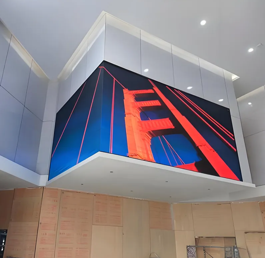
At handover, the wall should no longer be judged as a collection of individually installed cabinets. The finished display has to read as one visual plane from the intended viewing area. Small alignment differences that appear harmless during assembly may become obvious when the screen shows a bright uniform field.
Start with the approved reference: drawings, shop drawings, mock-up decisions, final cabinet layouts, accepted finish expectations, and any project-specific tolerances. If a numerical limit was never approved, final handover is not the right stage to invent one.
For an installed LED Wall Panel system, flatness, visible seams, and cabinet-to-cabinet offset should be recorded separately. They may influence one another, but they do not describe the same condition.
Flatness needs more than one viewing angle
A wall can appear acceptable from the centre and still reveal a wave or cabinet step from an oblique position. Check both the normal viewing zone and relevant side angles. Where the project uses a defined straightedge or another agreed checking method, use it to locate local high and low points rather than relying only on a frontal photograph.
Record the location and direction clearly. “Upper-right area uneven” is difficult to act on. A stronger entry identifies the screen zone, cabinet row and column, affected edge, visible symptom, and viewing direction. Light test content can help too: dark video may hide a small step that becomes immediately visible on white or light gray.

A visible seam is not automatically a gap problem
A cabinet joint may become visible because of physical spacing, edge height, module position, brightness difference, color difference, calibration, or several conditions together. Use more than one test image before deciding what the problem actually is.
White content can expose dark or bright boundaries, while mid-gray may reveal subtler cabinet differences. Moving content helps determine whether the seam remains noticeable in normal playback. A single local boundary also means something different from a repeating line at every cabinet joint.
Photographs should preserve context. For an important defect, capture a full-wall reference, a zone-level image, and a closer detail when necessary. A close-up alone may prove that a line exists without showing where it sits on the display.
Record cabinet displacement by direction
Cabinet offset can appear as horizontal shift, vertical shift, rotation, or front-to-back displacement. Directional wording such as “left cabinet forward at right edge” is far more useful during rectification than “cabinet misaligned.” Keep module-level face differences separate as well: a cabinet can sit correctly while one module stands proud or recessed.
Record Pixel Defects, Color Shift and Brightness Variation So They Can Be Retested
Identifying an abnormal point is only the first step. The record should show what appeared, where it appeared, under which test image it appeared, and whether the same condition remained after corrective work.
Dead points, dim points, intermittent faults, color-channel problems, local tint changes, cabinet-level brightness differences, and broader uniformity issues should not all become “bad pixel” entries. The description has to be specific enough for another technician to find and retest the same problem.
Point faults and area-level uniformity faults need different records
A dead point may fail to produce the expected output, while a dim point still operates at a lower visible level. Some channel faults only appear on specific red, green, blue, white, or mixed fields. Broader rectangular or cabinet-shaped changes should be treated as uniformity findings instead of isolated pixel faults.
Test content belongs in the record because the same problem may appear differently from one image to another. A point that looks acceptable on red may fail on blue; another may be difficult to see on white but obvious at low gray.
Build a defect map that still makes sense after the site visit
A useful defect map should allow another project team member to return to the same location without rediscovering it. A screen zone, cabinet coordinate, module position where useful, test image, photograph reference, and current status are usually enough.
Intermittent behavior deserves its own note. “Constant,” “intermittent after runtime,” or “appears during source change” can be more useful than another close-up image because each condition suggests a different retest.
When several points appear in one area, one clearly marked overview can reduce unnecessary duplicate photographs. Add detail images only where they help identify or verify the defect.
Do not invent a universal dead-pixel or uniformity limit
Rejection limits should come from approved commercial, technical, or project documentation. The same principle applies to color difference, luminance variation, seam tolerance, and other measurable conditions.
Different pixel pitches, viewing distances, applications, approved samples, and contracts can use different acceptance criteria. Where a numerical criterion exists, reference it. Where it does not, document the observed condition and route the decision through the agreed project process.
Instrument readings also need context. Meter type, position, test patch, measurement geometry, screen operating state, ambient condition, and calibration status can all affect comparison.
Use White, Grayscale and Dynamic Video to Expose Different Failure Modes
One attractive demonstration video cannot expose every problem. White, grayscale, and moving content challenge the display in different ways and should remain separate parts of the acceptance sequence.
White Field
Best for visible seams, broad brightness differences, obvious tint shifts, isolated dark points, and overall surface continuity.
Grayscale
Best for low-level tint differences, subtle cabinet boundaries, banding, and inconsistencies that high brightness may conceal.
Dynamic Video
Best for mapping continuity, processing, motion behavior, scaling, transitions, and the real project playback chain.
White-field testing removes visual distractions
A full white image makes broad brightness differences, cabinet boundaries, tint, dark points, and some geometric inconsistencies easier to compare. Keep the field static while checking the defined observation positions, and avoid large changes in framing or exposure when capturing before-and-after evidence.
Grayscale reveals what full brightness can hide
Low and mid-gray content can reveal tonal inconsistency, low-level tint, banding, and cabinet boundaries that disappear on a bright white screen. A grayscale ramp adds another useful check because it shows how the display transitions from dark to light instead of testing only one fixed level.
Dynamic video tests the complete visual chain
Moving content introduces texture, gradients, shadows, scaling, transitions, and motion. Slow pans are often more revealing than fast edits because repeated cabinet boundaries, interrupted lines, or mapping changes remain visible long enough to follow.
Where practical, use the real approved project path: the intended playback device, processor, switching route, controller chain, and normal display configuration. Acceptance should prove that the installed workflow operates correctly, not merely that an unrelated source can produce an image.
Keep the sequence repeatable after correction. If an issue first appeared at low gray, do not close it only because normal promotional video now looks acceptable. Significant changes in brightness, calibration, processing, color settings, or input route should also be recorded.
Include Control Redundancy, Temperature and Stable Runtime in Acceptance
Visual quality alone does not complete handover. Once surface condition, pixel performance, and test imagery look acceptable, the operating layer needs its own evidence. The normal signal path, approved backup functions, monitoring data, restart behavior, and runtime stability should match the actual project architecture.
Not every installation uses the same controller, monitoring function, redundancy method, or signal topology. Test only what belongs to the approved project configuration rather than turning handover into another design review.
Confirm the normal operating path before testing backup behavior
Confirm the actual input source, processing, controller path, data distribution, receiving system, and screen mapping. A numbered grid can expose swapped zones or mapping errors that natural content may hide.
If source switching belongs to the agreed scope, record the source, input route, processor or controller reference, active path, observed result, and any abnormal screen behavior.
Redundancy has to work, not merely exist on a drawing
Where a backup path is specified, trigger the actual changeover. Record the primary route, backup route, how the failover was introduced, what appeared on screen, whether alarms were generated, and how normal operation returned.
Recovery behavior should match the approved design. Some systems return automatically to the primary route; others intentionally remain on backup until a controlled manual action occurs.
Temperature only matters when the operating context is known
A single temperature number is rarely useful by itself. Where thermal status forms part of the project review, connect readings to cabinet or equipment location, runtime, screen state, ambient condition, and any warnings. Representative centre, edge, or enclosed zones may be more useful than collecting every available reading.
A stability run should resemble real use
A static image left on screen for an extended period provides limited evidence. Where relevant, use representative project content, live inputs, source changes, scaling, scheduled playback, playlists, or other functions that belong to normal operation.
Record resets, black sections, intermittent modules, flicker, signal loss, communication faults, unexpected restarts, and warnings. Timestamps make these events easier to compare with controller logs, source changes, or power events.
Intermittent faults should remain open until the relevant condition has been retested. “Not seen again” is not the same as verified closure. Preserve the original time, location, content, operating condition, and symptom even if the fault cannot be reproduced during the final visit.
Convert Site Findings into a Punch List and Final Sign-Off
The final stage turns technical observations into controlled closure. A project can otherwise accumulate photographs, messages, verbal promises, and repeated visits while still lacking one reliable handover status.
A useful Punch List connects each observation to its location, acceptance basis, corrective action, retest condition, evidence, and final status. The purpose is not paperwork for its own sake. It ensures that the project does not depend on memory when the same defect is reviewed days or weeks later.
Use one record structure for different types of defects
Flatness, seam, pixel, color, controller, and stability findings need different technical descriptions, but the underlying record can use the same fields. This makes the final register easier to filter, retest, and approve.
| Field | What to Record | Why It Matters |
|---|---|---|
| Item ID | Unique Punch List reference | Connects evidence, discussion and retest |
| Date / Time | Observation timestamp | Connects intermittent faults with runtime or logs |
| Screen Location | Zone, row, column, cabinet or module | Makes the finding reproducible |
| Defect Class | Flatness, seam, offset, pixel, color, brightness, control or stability | Prevents vague descriptions |
| Test Condition | White, gray, RGB, video, grid, source path or runtime condition | Allows the original fault to be recreated |
| Acceptance Basis | Approved drawing, specification, mock-up or project criterion | Avoids invented tolerances |
| Evidence | Photo, video, log, screenshot or measurement | Supports later review |
| Corrective Action | What changed, where and when | Preserves rectification history |
| Retest | Repeated content, position, route or runtime condition | Proves closure under comparable conditions |
| Final Status | Closed, accepted with note, pending or open | Controls final handover |
Describe the symptom before diagnosing the cause
“Vertical dark boundary visible on mid-gray field” is a stronger initial record than immediately deciding that the cabinet needs calibration or structural adjustment. Diagnosis may change during investigation; the original observed condition should not.
Corrective work is not the same as closure
The action field records what changed. The retest shows whether the change produced an acceptable result. A seam discovered on white should be tested again on white, and a low-gray uniformity problem should not close only because normal video looks better.
If calibration, brightness, mapping, color settings, or processing changed globally, extend the retest beyond the original local area whenever that adjustment could affect the wider display.
Keep closed items, accepted deviations and open items separate
An accepted deviation should remain identified as an accepted deviation. An unresolved condition should remain open. Where conditional handover is permitted, the outstanding register should identify ownership, current status, next action, and the follow-up route.
Final sign-off should point to one controlled evidence package
The final package may include the screen map, visual test record, pixel and uniformity record, control-system test, stability record, Punch List, rectification history, retest evidence, accepted deviations, and outstanding-item statement. Use consistent screen coordinates, clear revision status, and evidence file names that connect back to the relevant Punch List item.
Before final sign-off
Confirm the approved acceptance basis, make sure every open item has an owner and status, verify that corrected defects were retested under comparable conditions, and issue one clearly identified final revision of the handover record.
FAQ
Who should approve the final LED wall acceptance record?
Can an LED wall be handed over with open Punch List items?
What should be retested after replacing an LED module or cabinet?
Make Final Handover an Evidence Decision
A completed LED wall should reach final approval only after physical appearance, pixel condition, test imagery, controls, operating stability, and open findings have been reviewed as one connected record.
A useful LED wall acceptance checklist should show what passed, what required correction, what changed, and how the final result was verified. Where supplier-side cabinet information, project configuration, or product documentation still needs confirmation, review the relevant LED wall supplier solution information separately.
Need a Project-Specific Acceptance Checklist?
Prepare the wall layout, cabinet or module references, approved visual criteria, intended viewing positions, planned test content, controller topology, redundancy design, stability-run requirements, and current Punch List format.
With those details confirmed, the checklist can follow the same logic from first observation through rectification, comparable retesting, and final approval.
Request Acceptance Checklist Fields