EN
EN

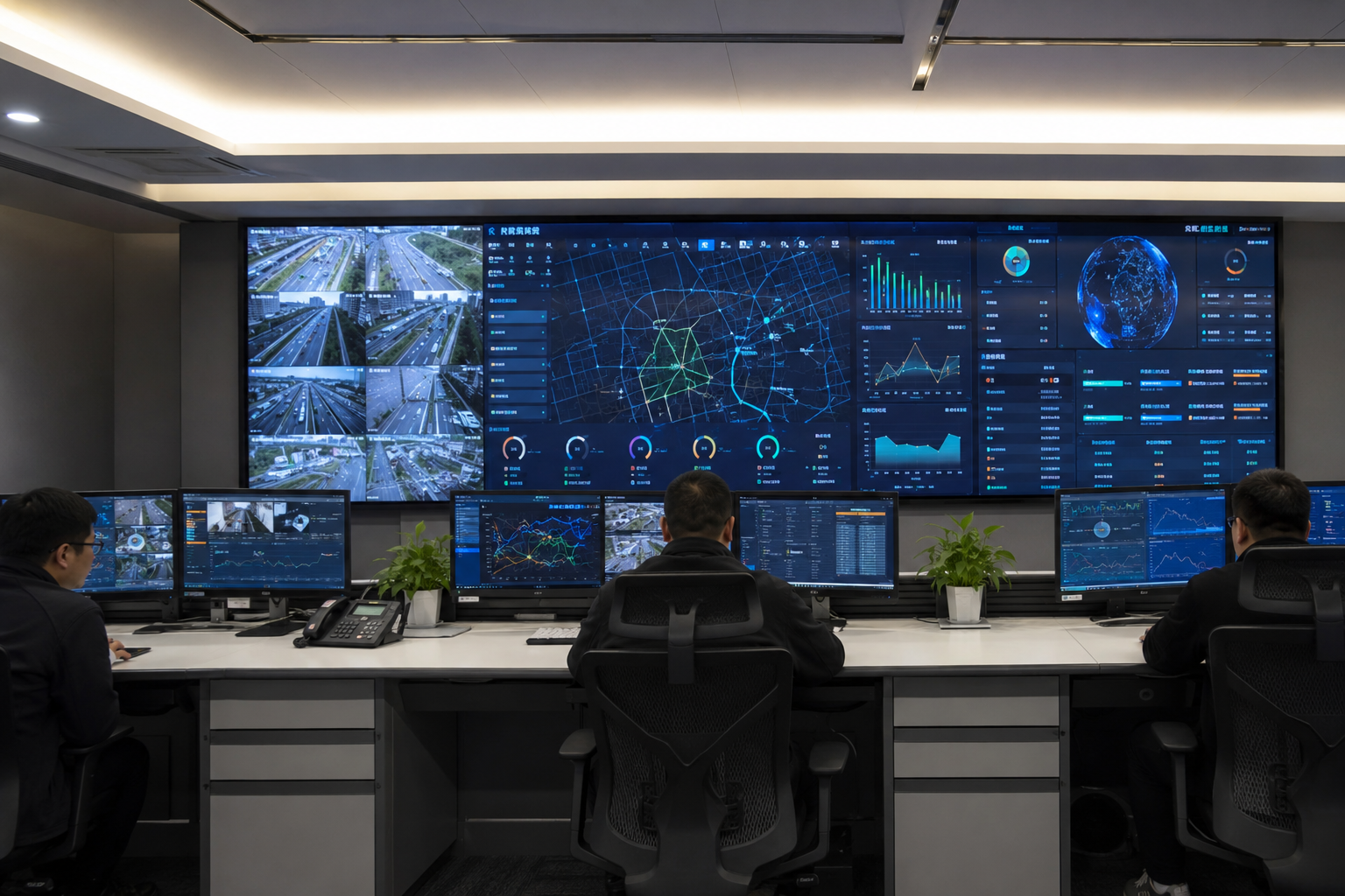
A control room LED video wall earns its value when the room becomes busy. A map expands across the wall. Camera feeds remain open. Alarm text appears beside live operating data. At that moment, a visible seam, unreadable label, failed signal path, or slow repair process stops being a specification issue and becomes an operating problem.
That is why the LED-versus-LCD decision should begin with the room at work, not with a product sheet. The closest seat, the smallest critical label, the normal source layout, the longest shift, and the expected recovery time all matter more than a single headline number.
This guide follows the decision in the same order a project team should: what the wall must show, how it feels during daily operation, what happens after a fault, how service affects the room, and which information is needed before a recommendation can be trusted.
|
LED usually deserves priority
Large maps cross the full wall, layouts change during incidents, unusual wall dimensions matter, or local faults must affect the smallest possible picture area. |
LCD can remain the practical route
Camera groups stay inside fixed windows, the panel grid fits the workflow, native panel resolution is useful, and a known service process already exists. |
The deciding proof is operational
Run real content from the closest seat, remove one signal or power path, and time one repair from fault discovery to normal layout restoration. |
1. The Cheapest Display Wall Can Become the Most Disruptive One
A quotation normally places the visible hardware at the center. Daily operation does not. The room experiences the whole system: display surface, controller, source network, mounts, power distribution, UPS, racks, cooling, cable routes, monitoring tools, spare parts, and the service path around the wall.
A lower initial figure can still create a higher operational cost. A shallow room may lose valuable floor area to a rear corridor. A controller with limited headroom may block future layouts. A replacement part may remain unavailable when a visible fault appears. Each issue adds time, labor, or disruption after installation.
Picture the first fault, not the first demo
A showroom demo starts with a clean source and a prepared operator. A real fault arrives during a shift. The wall may already carry several camera groups, a shared map, and an alarm panel. The room then needs an answer to four practical questions:
- What disappears? One pixel area, one module, one complete panel, one signal group, or the entire wall?
- What remains usable? Can critical sources move to another area without rebuilding the layout?
- Who acts first? Does the room switch automatically, follow a short procedure, or wait for a specialist?
- When is the room normal again? The useful time includes diagnosis, access, replacement, calibration, and content restoration.
These questions turn “reliability” into something measurable. They also make quotations easier to compare. Two walls may have similar dimensions, yet one may isolate faults, preserve critical content, and restore service much faster.
Room geometry can change the real price
A front-service design can save depth, but service then happens from the operating side. Consoles, floor protection, lifting access, and safe working space still need planning. A rear-service wall moves activity away from the room, yet it needs a practical corridor with lighting, ventilation, and access to every section.
Wall height matters too. A repair near the ceiling may require a platform or temporary closure of nearby seats. Rack location affects cable length and response time. UPS placement affects heat and service access. These are not secondary details; they shape the full life of the installation.
The project brief should contain the information below. Without it, a low price may simply describe a smaller scope.
| Room facts: width, depth, clear height, wall construction, console rows, seated eye level, and service access. | Viewing facts: closest, typical, and farthest working distances rather than one approximate distance. |
| Content facts: source count, source resolution, normal layouts, incident layouts, and the smallest critical label. | Availability facts: operating hours, UPS expectation, critical feeds, acceptable disruption, and fallback layout. |
| Service facts: front or rear access, spare storage, technician route, allowed maintenance window, and local support model. | Growth facts: future source count, expected layout changes, possible wall expansion, and controller headroom. |
2. When LCD Seams Become an Operating Problem
A physical bezel is not automatically a reason to reject LCD. In a room built around fixed camera groups, each panel can hold one or more windows. The grid becomes part of the layout, and the room may work comfortably for years.
The problem appears when the content stops respecting the grid. A regional map expands during an incident. A process diagram fills the wall. A remote desktop stretches across several panels. Labels split at the joints, thin route lines disappear, and moving objects seem to jump from one panel to the next.
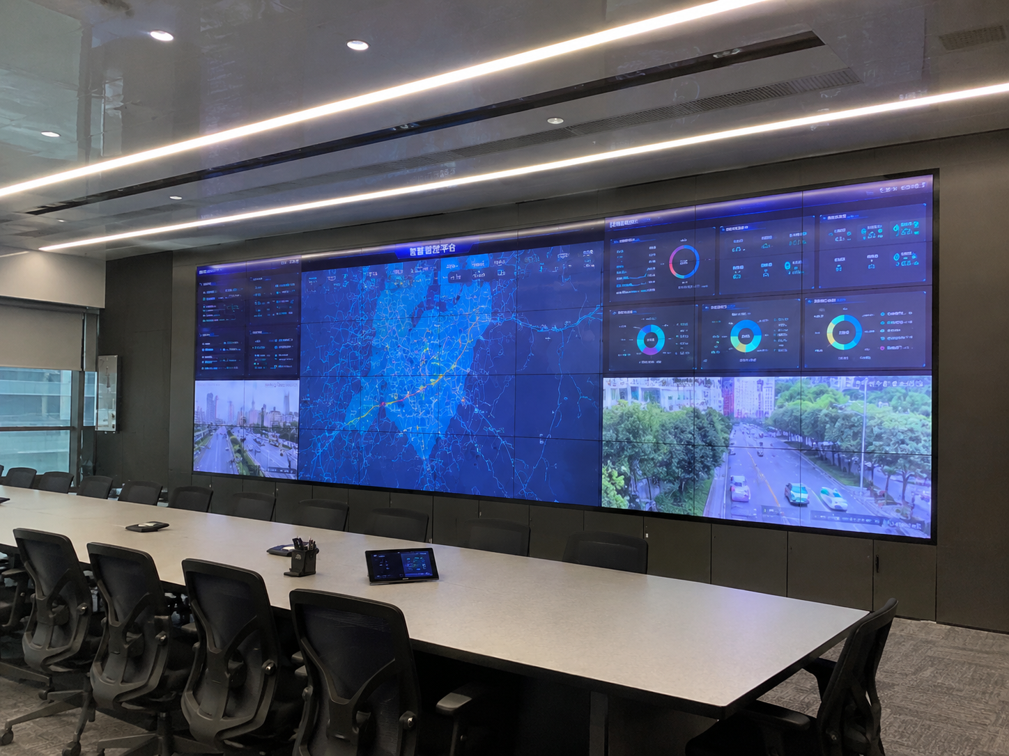
Compare Indoor LED Display Systems
The best choice depends on how layouts change
LCD can be efficient when the normal layout stays stable. Camera windows can align with panel boundaries. Alarm text can remain inside safe areas. Operators become familiar with the same arrangement.
A continuous LED canvas becomes more valuable when the room frequently enlarges sources or combines information across departments. Windows can move without avoiding a permanent grid. A shared map feels calmer because the eye follows the route rather than the hardware.
However, “seamless” should not be accepted as a slogan. Poor cabinet alignment can create a visible step. Weak calibration can produce patches on gray backgrounds. Module edges may appear when mechanical tolerances or brightness matching are inconsistent.
Run a content rehearsal before choosing the technology
A useful rehearsal takes less time than another specification meeting. The room should prepare three layouts: the normal daily view, a full-wall critical source, and a busy incident view with alerts, camera feeds, maps, and communication windows.
The team then watches from the closest seat, the main operator row, and the farthest working position. The review should note where seams interrupt labels, where thin lines disappear, where important symbols become crowded, and whether the eye can locate priority information quickly.
When the room mostly shows independent windows, LCD can remain practical. When the room often turns many sources into one shared operating picture, a seamless LED screen carries much greater value.
This rehearsal can also expose a dashboard problem rather than a display problem. Thin fonts, weak contrast, crowded labels, and decorative lines remain difficult on both technologies. Correcting the interface may improve recognition more than increasing the hardware specification.
3. How to Judge Pixel Pitch and Close-View Clarity Before Ordering
Resolution decisions often start with one number. A smaller LED pixel pitch sounds safer. A larger LCD pixel matrix sounds more detailed. Neither answer is complete until the smallest important information appears at the smallest normal window size.
The critical item may be a timestamp, map label, alarm code, equipment tag, chart legend, or short value inside a process graphic. That item should lead the test because it reflects the actual task. Promotional video hides pixel structure much more easily than small text and thin lines.

View Fine-Pitch LED Display Options
Three viewing positions reveal three different risks
The closest seat reveals pixel structure, rough text edges, and scaling artifacts. The main operator row reveals whether the wall feels comfortable during normal work. The farthest position reveals whether priority information remains large enough to recognize without moving closer.
For that reason, one “average viewing distance” is not enough. The project file should record the closest, typical, and farthest positions. Each position protects a different part of the experience.
Wall size and native pixel count belong in the same line
A large wall can still offer limited data space. A smaller wall with a finer pitch may show more useful detail. Every proposal should therefore list the active width, active height, and total native matrix together.
The source path matters as much as the display. A computer may scale the source once. A decoder may scale it again. The wall controller may scale it a third time. Repeated scaling can soften text and thin lines even when the wall has enough pixels.
- Load the normal multi-window layout instead of one full-screen image.
- Include the smallest label, timestamp, alarm code, and map line that still matters.
- Set the wall to the expected operating brightness, not the demonstration maximum.
- Review the same content from the closest, typical, and farthest positions.
- Reduce one important source to its smallest normal window.
- Approve the content only when the information remains readable without leaning forward or changing the layout.
Interface design can save more than another hardware upgrade
Bolder text, stronger contrast, clearer spacing, and fewer decorative lines often improve recognition immediately. Critical labels should not sit against window edges. Alarm colors should remain distinct against both normal and dark backgrounds.
The display and the application should be tested together. Otherwise, a project can spend heavily on a fine pitch LED display while leaving the actual dashboard difficult to scan.
4. What the Wall Feels Like After Six Hours Matters
A control room is not a retail showroom. The wall does not need to dominate the room every minute. It needs to remain easy to read while operators repeatedly move their eyes between desktop monitors, consoles, and the shared display.
A wall that looks impressive for five minutes can feel harsh during a long shift. Bright white dashboards may create glare. A large brightness difference between the wall and desktop monitors forces the eyes to keep adapting. Reflections can hide labels that were clear during installation.
Comfort begins with the room, not the brightness setting
Ceiling lights, windows, glass partitions, glossy furniture, and task lights all affect the display. A bright fixture reflected near a map label can remove useful detail. A window behind the consoles can force one setting during the day and another at night.
The site review should therefore include different lighting conditions when they exist. Photos taken from seated eye level often reveal reflections that a simple room measurement misses. Standing positions and side views matter in rooms where supervisors or visitors regularly use the wall.
Low-brightness quality matters more than peak output
Many operating interfaces use dark backgrounds. Small colored indicators, thin grids, and night-camera detail sit close to black. If the display loses those shades when dimmed, the wall becomes less useful even though its peak output looks strong.
LED performance at lower brightness depends on the selected modules, processing, driver behavior, and calibration. LCD performance depends on panel behavior, backlight control, viewing angle, and calibration. The proposed configuration should be tested at the expected room setting.
- A bright dashboard with small dark text
- A dark interface with small colored indicators
- Night-camera footage with low-level detail
- The normal mixed-source layout
- The wall beside desktop monitors at their real settings
- The same review after the room has operated for several hours
Uniformity also shapes comfort. A warmer panel, brighter module, or visible patch can draw attention away from the content. The information may remain readable, yet the wall feels unsettled because the eye keeps noticing the hardware.
A consistent surface lets attention move across maps and dashboards without stopping at display boundaries. Calibration, spare matching, and replacement procedures should protect that experience throughout the service life.
5. 24/7 Reliability Means Knowing What Happens After One Failure
A display surface can remain healthy while the room loses a controller, source link, network path, receiving path, or power circuit. That is why a 24/7 display system should be reviewed as a chain from source to light.
The design should begin with critical content. Not every source needs the same protection. A background presentation may tolerate a short interruption. An alarm summary, process overview, or emergency map may need an immediate alternate path.
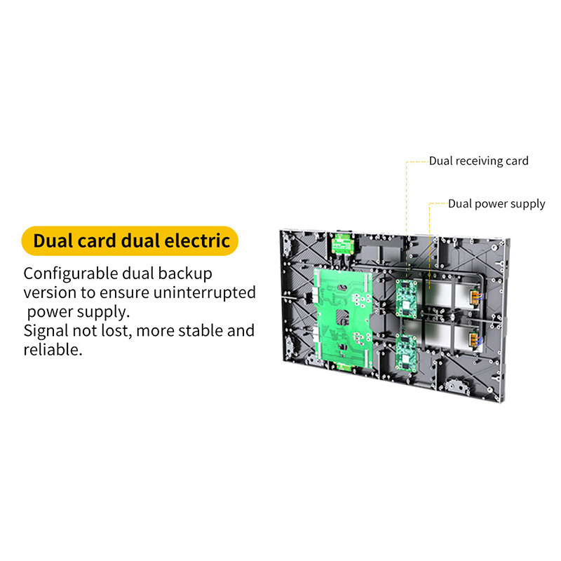
Review Cabinet and Backup Options
Two backup parts do not always create two independent paths
Two signal cables offer limited protection when both pass through the same switch. Dual power supplies offer limited protection when both connect to one circuit. A backup processor cannot help when it receives no alternate source. The system drawing should make these shared dependencies visible.
A clear drawing should show source devices, encoders or decoders, switches, processors, sending paths, receiving paths, wall sections, power circuits, UPS connections, rack locations, and the devices that share each point.
The room needs a visible recovery behavior
A backup feature has little value when the operating team does not know what happens next. The specification should describe the visible result. Does the wall switch automatically? Does an alert appear? Does the room continue with a reduced layout? Does one trained action restore the critical sources?
Automatic failover can reduce recovery time, but it still needs monitoring. Manual failover can also work when the procedure is short, practiced, and available on every shift. The right choice depends on the room’s operating model.
During commissioning, one path should be removed at a time under controlled conditions. The test can disconnect a critical source path, disable a processor output, isolate one power feed, and then restart the system after a simulated outage.
The wall response should match the written recovery plan. Critical information should remain visible or return within the accepted time. Any manual step should be clear enough to perform during a busy shift.
UPS planning should protect the operating outcome
Some rooms need enough runtime for generator transfer. Others need time for an orderly shutdown. A critical command room may need selected wall sections and processing equipment to remain active while nonessential areas turn off.
The power plan should separate display load, processing, network equipment, source devices, and control consoles where the recovery goal requires it. Startup behavior also matters. A wall that returns only after several manual resets may extend disruption long after power has stabilized.
6. Measure the Full Interruption, Not Only the Repair
A visible fault at 10:40 a.m. does not create a convenient maintenance window. The room may still be handling calls, camera feeds, and live data. The first task is often to protect the operating picture before anyone touches the wall.
LCD and LED differ most clearly in the size of the visual unit that usually receives service. An LCD wall commonly treats the complete panel as the main replacement unit. An LED wall can often isolate work to a module, receiving card, power supply, or cabinet section.
The size of the dark area changes the room response
A failed LCD panel creates a large rectangular interruption. The remaining panels may continue, but the missing area can remove a complete group of feeds. The controller may need a temporary layout that avoids the failed panel.
A failed LED module can affect a smaller area. That smaller fault domain may preserve more of the shared picture. However, a cabinet-level power or signal problem can still affect a larger section, so the project should map each fault honestly.
A smaller replacement part does not guarantee a short interruption. The real benefit appears only when the correct spare is available, the access method is practical, the technician knows the procedure, and calibration can be restored without a long investigation.
Front service and rear service create different room experiences
Front service can reduce wall depth and remove the need for a rear corridor. It also brings tools and activity into the operating room. Consoles, floor finishes, nearby seats, and safe lifting access still need protection.
Rear service keeps most work away from the operating floor. It requires enough corridor depth, lighting, ventilation, and a clear route to every component. A narrow or obstructed corridor can turn a simple repair into a long task.
LCD mounts need the same level of attention. A panel near the center of a large array may require careful removal and realignment. A replacement can disturb neighboring panels when the mount does not support precise access.
A working spare may still look wrong
A replacement display element may function electrically and still appear different. An LCD panel from another production period may not match the surrounding units. An LED module may show a visible brightness or color difference when matching data and calibration are not prepared.
Spare planning should therefore include labeling, storage, visual matching, calibration data, and a record of the wall section each spare supports. A quick repair that leaves one obvious patch still distracts from the operating picture.
- Detect and identify the fault.
- Move critical sources to a safe temporary layout.
- Protect the work area and retrieve the labeled spare.
- Reach the failed part using the planned service route.
- Replace the component and restore calibration or alignment.
- Return content to the normal layout.
- Confirm visual consistency and close the event record.
This timed exercise often changes the technology decision. A higher initial investment may produce a shorter and less disruptive service event. In another room, a familiar LCD platform with stocked panels and trained local support may recover faster. The useful comparison is the actual interruption, not the assumed repair method.
7. Choose the Route That Fits the Room, Content, and Support Model
No single technology wins every control-room project. The better route follows the way information moves across the wall, the distance from the nearest seat, the acceptable fault area, the service model, and the expected years of use.
| Decision Point | LED Route | LCD Route | Proof to Request | Decision Signal |
|---|---|---|---|---|
| Full-wall content | Continuous active canvas when alignment and calibration are correct | Permanent panel grid remains visible | Large map, moving object, wide desktop, and incident layout | Frequent shared layouts favor LED; fixed windows can suit LCD |
| Small text | Depends on active dimensions, pitch, processing, and scaling | Depends on panel matrix, array size, processing, and scaling | Smallest normal window at all three viewing positions | Choose the configuration that passes the real content test |
| Fault area | A module-level fault may affect a smaller picture area | A panel fault creates a larger rectangular gap | Controlled fault and fallback-layout demonstration | Critical rooms often value the smaller operational interruption |
| Service method | Can support module or component-level service | Often uses complete-panel replacement | Timed repair including access, matching, and content restoration | The local support model can outweigh the assumed hardware advantage |
| Room fit | More flexible active dimensions within cabinet geometry | Dimensions follow the panel array | Wall elevation, clear height, access path, and future opening | Irregular dimensions and phased growth often favor LED |
| Lifecycle scope | Close-view configurations may require a higher initial investment | Standard panel arrays may create a lower entry point | Equal scope for processing, structure, spares, power, training, and service | Compare complete systems, not display hardware alone |
Critical command or dispatch room
A critical room usually changes layouts during incidents. Large maps cross the wall. Several roles depend on the same operating picture. Maintenance windows are limited. LED often becomes the stronger candidate because the canvas remains continuous and local service can affect a smaller area.
That preference should still be earned through a readability test, a low-brightness review, a fault rehearsal, a spare-matching plan, and a timed service exercise. A poorly designed LED system does not become suitable simply because the room is critical.
General monitoring room
A general monitoring room may use stable camera groups while detailed investigation happens at individual workstations. In that setting, the visible grid may carry less operational cost. LCD can remain practical when the panel array fits the wall and the local service process is familiar.
The proposal should still cover matching panels, controller redundancy, fallback layouts, access, and the full repair window. A low initial price should not remove those requirements.
Meeting and monitoring in the same space
A mixed-use room changes visual roles during the day. Monitoring mode shows several data windows. Meeting mode may place one presentation, remote participant, or dashboard across the complete surface.
LED often fits the full-wall presentation mode because the image is not crossed by panel borders. LCD may still work when presentation use is secondary and the normal layout remains segmented. Lighting, camera capture, audio, and presentation scaling should join the display review.
Turn the room into a one-page operating brief
A useful brief does not need to be complex. It needs enough detail to connect the room with the proposed wall. The following items allow a project team to compare LED and LCD on equal terms:
- Room width, depth, clear height, and wall opening
- Closest, normal, and farthest viewing distances
- Source quantity, source resolutions, and window count
- Normal, incident, meeting, and fallback layouts
- Daily operating hours and expected service life
- Critical feeds and acceptable recovery time
- UPS, backup-path, and restart expectations
- Front or rear maintenance preference
- Rack position, cable routes, and cooling conditions
- Spare storage and local service arrangement
A four-step approval sequence
- Confirm the room facts. Do not shortlist technology while viewing distances, wall dimensions, or service access remain uncertain.
- Run real content. Use the normal window count, the smallest critical information, and an incident-wide layout.
- Test one failure and one repair. Observe what disappears, what remains available, and how long normal operation takes to restore.
- Compare equal lifecycle scope. Include structure, processing, power protection, spares, training, maintenance access, support, and future expansion.
Move from Comparison to Project Preparation
01
Project Intake
LED Video Wall Project Intake GuidePrepare structure, service access, power, signal routing, backup expectations, and site information before quotation. Open the Intake Guide |
02
Readability Check
Return to the Closest-Seat TestRecheck the smallest normal label, source window, scaling path, and farthest-seat text size. Review Clarity Steps |
03
Service Check
Return to the Full Interruption TestRecheck fault area, fallback layouts, spare matching, access direction, and restoration time. Review Service Steps |
Control Room LED vs LCD FAQ
Send the operating facts before choosing the display technology
Send room dimensions, closest viewing distance, signal quantity and operating hours for an LED-versus-LCD video wall recommendation. Include the normal layout, installation environment, critical feeds, backup expectation, and preferred service direction where available.
The useful starting package: a room drawing, three viewing distances, one screenshot of the normal layout, source count, operating schedule, and the acceptable recovery time.
With those facts, a control room LED video wall can be compared with LCD on the points that affect daily operation: readable content, fault area, recovery behavior, service access, and lifecycle scope.
Send Project Details to the Project Team