EN
EN

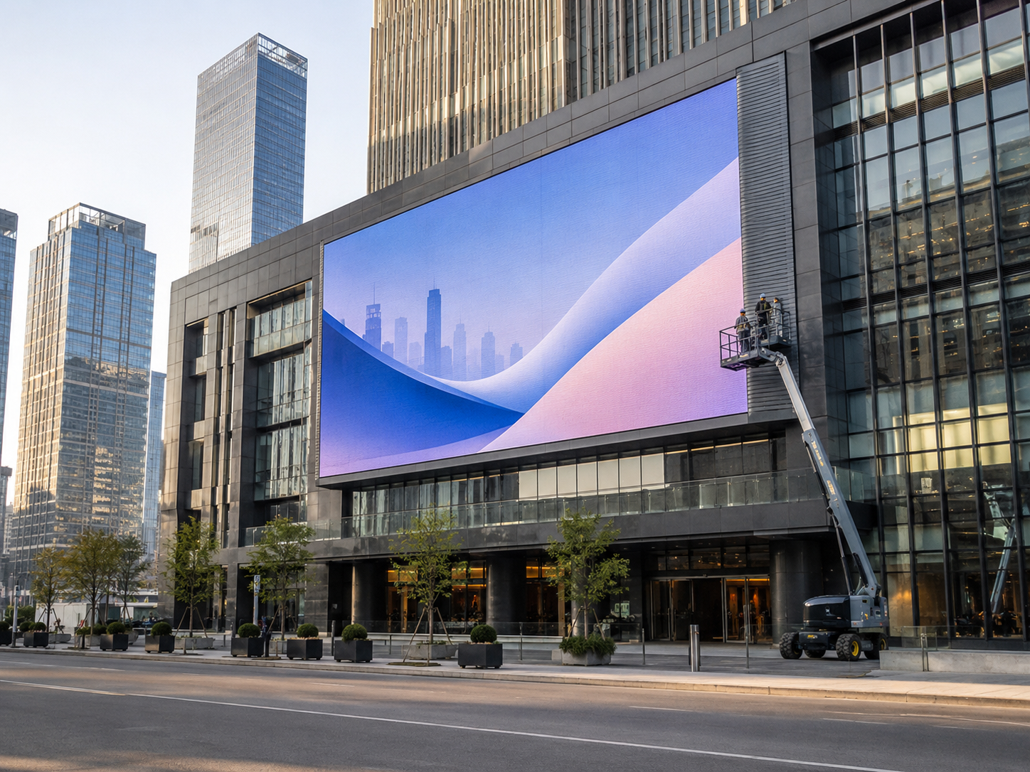
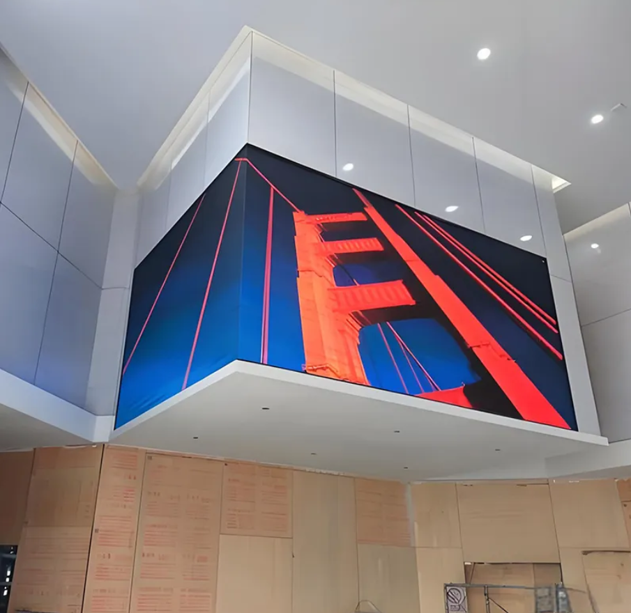
A building facade LED display may look effortless after sunset. From the street, the finished image appears clean and simple. Behind it, steel brackets cross architectural layers, cable routes pass through weather barriers, warm air gathers in narrow cavities, and a safe route must remain available for future repairs.
Those hidden conditions usually decide whether the installation remains practical after handover. A cabinet specification cannot explain where structural loads enter the building. Likewise, a waterproof label cannot show where rainwater travels after reaching a frame ledge, wall penetration or cable gland.
A reliable facade project therefore begins with the building itself. Wall construction, curtain wall movement, wind exposure, sunlight direction, maintenance access, electrical zoning and local approval should shape the screen package before fabrication starts.
What the project is really choosing
The visible screen is only one layer of the decision. A shallow front-service installation may preserve a clean elevation, yet it can leave little room for cable bends, distribution boxes and heat release. A deeper rear-service frame can simplify repairs, although it changes the building profile and increases the structural offset.
The practical objective is not to select the largest or brightest specification. It is to create a screen that fits the elevation, remains readable through changing light, releases water and heat, and can still be serviced without dismantling unrelated parts of the building.
How Building Facade LED Display Planning Changes by Facade Type
Architectural elevations often show a smooth finished surface. On site, that surface may hide insulation, stone cladding, glazing rails, waterproof membranes, fire barriers or an open steel lattice. Each layer changes where brackets can sit and how technicians reach the screen later.
For that reason, the visible facade should not become the assumed load-bearing surface. The first useful section drawing shows the screen, the complete facade build-up and the nearest verified structural member together.
Solid walls: straightforward from a distance, layered at close range
A concrete or masonry elevation may appear to offer simple mounting. However, many finished walls include stone panels, render, insulation or a ventilated cavity before the primary structure begins.
Consider a commercial elevation that appears to be solid concrete. A controlled survey opening may reveal stone panels fixed to small rails, followed by insulation and a waterproof layer. The original short-anchor concept no longer reaches a dependable substrate. It may also penetrate the weather barrier without a suitable sleeve or flashing detail.
In this condition, brackets should transfer loads to verified concrete, structural masonry or approved steelwork. Meanwhile, each penetration needs a weather detail that works with the existing wall system rather than depending on a final bead of sealant.
Solid walls often suit shallow front-service layouts. The display can remain close to the elevation, and no permanent rear walkway is required. Still, a shallow cavity leaves limited space for cable loops, local isolators and warm-air movement. These elements must fit in the section before the cabinet depth is approved.
Glass curtain walls: movement and replacement access matter
Glass panels and decorative mullion caps rarely provide the main structural support for a large display. The mounting system normally needs to reach slab edges, columns, roof steel or dedicated facade brackets.
Curtain wall systems also move. Thermal expansion, inter-story movement and glazing tolerances allow the envelope to respond without damaging glass. A rigid screen frame that crosses those movement zones can create unwanted forces or restrict the facade.
The curtain wall consultant should review bracket positions, fixed points, sliding points, drainage cavities and removable glass zones. This review becomes especially important when the screen frame crosses several facade modules.
The experience inside the building matters as well. An opaque screen can darken a lobby, block an outward view or cast changing light across interior finishes. A transparent arrangement may preserve more daylight and visual connection. However, it still requires an organized support frame, cable routing and safe service access.
A useful design question is simple: can the glass behind the screen still be cleaned or replaced? If the answer requires removing most of the display, the interface remains unresolved. Side extraction, removable frame sections or planned access bays may create a more practical long-term arrangement.
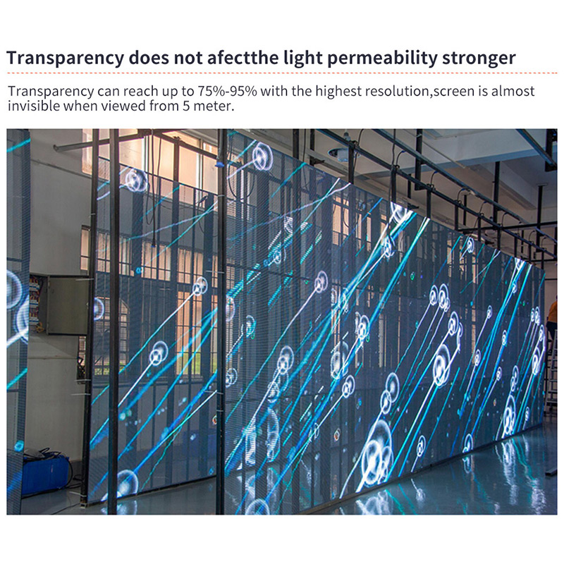 A transparent screen can preserve more daylight, but bracket positions, cable routes and glass replacement access still require coordinated sections. View Transparent LED Display Options
 Open grids and architectural mesh: more airflow, more exposure
Perforated metal, expanded mesh, fins and open steel grids can provide airflow behind the display. At the same time, they expose the rear surface to wind-driven rain and changing pressure.
An architectural grid may look strong while serving mainly as a decorative layer. Visual inspection cannot confirm its capacity. Member sizes, connection details and engineering responsibility should be identified before the grid becomes part of the screen support.
Open facades also reveal workmanship. Cable trays, distribution boxes and service loops may remain visible from nearby buildings or interior spaces. The rear arrangement should therefore be planned with the same discipline as the front edge.
| Decision point | Solid wall | Glass curtain wall | Open grid or mesh |
|---|---|---|---|
| Likely support | Concrete, structural masonry or secondary steel | Slab edge, columns, roof steel or approved brackets | Primary steel or a separately verified frame |
| Main hidden risk | Cladding cavities, waterproof layers and uncertain substrate | Movement, blocked drainage and glass replacement | Rear wind exposure and decorative members with limited capacity |
| Maintenance tendency | Front service when projection is limited | Front, side or mixed access after facade review | Rear access where a safe walkway exists |
| Water concern | Penetrations and trapped water behind brackets | Curtain wall weep paths and pressure cavities | Rain approaching from the front, sides and rear |
| Critical early document | Wall section and confirmed anchor substrate | Curtain wall shop drawings and slab-edge sections | Structural grid and access-platform drawings |
Screen Weight, Steelwork, Anchors and Wind Load
Equipment weight is not the complete installed load. Secondary steelwork, brackets, perimeter trims, cable trays, local electrical boxes and access platforms also affect the building connection.
Frame projection matters as well. Once cladding depth, alignment tolerance, rear ventilation and cable space are included, the screen may sit farther from the primary structure than the front elevation suggests. That offset can increase bending at the brackets.
Trace the complete load path
A coordinated drawing should allow every load to be followed. Cabinets connect to rails. Rails connect to secondary steel. Secondary steel transfers forces through brackets and anchors into verified structural members.
Decorative stone, insulation, facade caps and non-structural mullions should not become accidental load-bearing components. When a facade element is intended to carry load, its capacity and engineering responsibility should be stated clearly.
A visible load path also makes quotations easier to compare. One proposal may include cabinets and rails only. Another may include anchors, structural brackets and access steel. A lower figure can therefore represent a smaller scope rather than a more efficient solution.
Wind acts in more than one direction
Wind can push the screen toward the facade, pull it outward and create twisting around corners or stepped elevations. Repeated movement can also affect alignment, fasteners, cable loops and perimeter seals.
The design basis depends on building height, terrain, topography and screen position. Corner zones and roof edges can behave differently from the center of a lower elevation.
Screen construction changes the pressure response too. A closed cabinet wall does not behave exactly like an open mesh arrangement. Air may pass between modules, through cabinet gaps or behind perimeter covers. The engineer therefore needs the real cabinet and frame concept.
The effect is easy to understand at height. One cabinet feels rigid in a workshop. Across a large exposed elevation, hundreds of connected panels receive repeated gusts. Small clearances can rattle, flexible covers can move, and unsupported cables can strike nearby steelwork.
Existing buildings require verified anchor conditions
Original drawings may not reflect later repairs, facade replacement or undocumented services. Anchor zones may therefore require scanning, controlled openings or testing defined by the structural engineer.
Edge distance and base material also influence the connection. Reinforced concrete, structural steel and masonry require different details. A convenient drilling point may still be unsuitable because it sits near a slab edge, repair zone, embedded service or curtain wall anchor.
Waterproofing should be reviewed at the same time. A bracket can be structurally acceptable while damaging a membrane or blocking a drainage cavity. Structural and facade reviews should meet before the final penetration detail is issued.
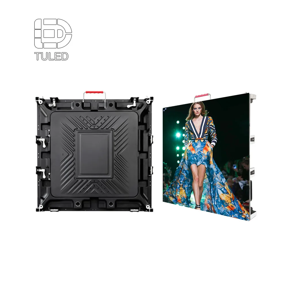
 Front and rear cabinet views help reveal handling points, frame depth and the working space needed around locks, connectors and removable components. View Outdoor Cabinet Details
 Steelwork should support installation and later repair
The secondary frame establishes line, level and cabinet alignment across a facade that may not be perfectly flat. Controlled adjustment points should therefore be included in the connection detail.
Adjustment should still have limits. Long unsupported bolts, stacked washers and improvised packing can create unstable connections. Approved tolerance zones and packing materials should be defined before installation.
The completed frame must also allow component removal. A cabinet may fit during initial assembly and become trapped after perimeter trims, cable trays or weather covers are installed. A representative extraction sequence should be tested during drawing review or mock-up work.
Questions to answer before structural pricing
- Which verified building members receive the screen loads?
- Which party designs and supplies the anchors, brackets and secondary steel?
- What screen, frame, platform and temporary lifting loads are included?
- Which wind, movement and deflection conditions will be reviewed?
- How far does the finished screen project from the structural support?
- Which movement joints or facade zones must remain independent?
- Which surveys or tests remain open before fabrication?
Sun Direction, Daylight Visibility and Night Dimming
A facade screen changes character throughout the day. Morning light may strike one side of the elevation. At noon, bright sky and reflected glass can reduce contrast. After dark, the same output can feel far stronger against a quiet street.
Brightness planning should therefore begin with the actual elevation, not a generic outdoor category. Orientation, neighboring buildings, viewing direction, operating schedule and content style all shape the final result.
Map solar exposure before selecting the operating range
An east-facing screen may experience low morning sun. A west-facing elevation may be most difficult in late afternoon. Nearby towers, canopies and trees can create moving shadow patterns that change through the year.
Direct sun on the screen is only part of the issue. A bright sky behind the viewing position can also reduce perceived contrast. Reflections from nearby glass may create another difficult angle.
A useful survey records the screen direction and intended viewpoints. Photographs taken at different times can reveal changing glare. A short site video may also show how shadows move across a plaza or transport route.
Daytime capability should not become permanent maximum output
A high brightness LED display may require strong daytime capability. However, the highest available setting should not become the normal setting at every hour.
During the day, the screen competes with sunlight and bright reflections. After sunset, the surroundings become darker. White content that looked balanced at noon may illuminate nearby glass and attract attention far beyond the intended viewing zone.
A practical control plan can include daylight, dusk, evening and late-night profiles. Automatic sensing may support gradual adjustment, although the sensor must not sit in permanent shade or receive light directly from the display.
Scheduled dimming adds consistency. It also allows approved operating periods to remain stable. Manual override can remain available for authorized operations, but the responsibility and reset procedure should be documented.
| Operating period | Typical visual condition | Useful response |
|---|---|---|
| Morning | Low-angle light and changing shadows | Use a gradual increase and review east-facing glare |
| Midday | Bright sky and strong reflections | Prioritize contrast and use only the required output |
| Dusk | Ambient light changes quickly | Reduce output smoothly rather than in one visible step |
| Night | Dark surroundings and sensitive nearby windows | Apply the approved lower profile and content limits |
Content changes perceived brightness
Large white areas, fast flashes and hard transitions can feel much brighter than darker brand content at the same hardware setting. A single output number cannot describe the complete night-time impression.
Commissioning should therefore use representative content. The test loop can include white backgrounds, saturated colors, text, video and emergency messages. This reveals effects that a static color test may miss.
Viewing time matters too. A pedestrian plaza allows longer attention and more detail. A road-facing elevation may offer only a few seconds. Large shapes and shorter messages can improve communication without relying on excessive brightness.
Energy performance depends on operation as well as equipment
An energy saving LED display strategy should include dimming profiles, operating hours, content design and electrical zoning. Component efficiency remains important, but daily operation determines how often the display approaches its maximum demand.
For example, strong white content running through a low-traffic night period adds demand without improving the message. A calmer content schedule and lower night profile can reduce unnecessary output while improving the architectural experience.
Exact consumption should still come from confirmed product data and an agreed operating scenario. Maximum design load and expected daily use should be presented separately.
When comparing outdoor screen formats, viewing distance, cabinet arrangement, environmental exposure and maintenance direction should be considered alongside visual output.
Drainage, Ventilation, Heat Control and Corrosion
Rain rarely reaches a high facade in one neat direction. Wind can drive water across the front, around side edges and into the rear cavity. Runoff may also descend from the building above.
A waterproof outdoor LED screen still needs a complete drainage strategy. Cabinet protection is only one layer. Frame ledges, cable entries, wall penetrations and local electrical boxes must also guide water safely away.
Follow the water instead of assuming a dry cavity
The review should begin above the display. Water may run down facade panels, collect on a canopy or enter behind a perimeter trim. Horizontal steel members can then create small ledges where water and debris remain.
Cabinet rows also create runoff paths. Water leaving an upper joint should not discharge onto a lower connector, service door or distribution enclosure. Cable loops should direct moisture away from glands rather than toward them.
At the bottom, drainage openings need somewhere to discharge. They should not empty into a sealed architectural pocket or across a finish that will stain. The openings must also remain reachable after final trims are installed.
Curtain wall drainage requires particular care. Brackets and cables should not block pressure-equalized cavities or existing weep routes. The screen frame and facade envelope need one coordinated water section.
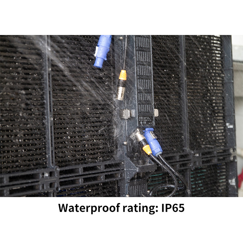 Panel-level water testing should be supported by suitable connector positions, cable loops, frame drainage and facade penetration details. Review Outdoor LED Display Systems
 Heat develops in the space that drawings often leave blank
The rear cavity may look open in a section while behaving like a warm enclosure after installation. Solar heat reaches the facade surface, electronics add internal heat, and decorative covers restrict airflow.
Natural ventilation needs a recognizable path. Cooler air should enter without passing through uncontrolled water routes. Warm air should leave without returning directly to the inlet.
Forced ventilation may help when the cavity is narrow or enclosed. However, fans and filters create future maintenance work. Their access panels should remain reachable without removing large portions of the display.
Nearby building systems also influence the layout. Warm discharge air should not enter windows, fresh-air intakes or smoke-control openings. The frame should not block an existing architectural louver.
Condensation can appear without visible rainfall
Daily temperature changes can produce moisture inside enclosures and rear cavities. A cool surface followed by warm humid air may create condensation even when the facade remains sheltered from direct rain.
Cable glands should match the actual cable diameter. Unused openings need suitable plugs, while electrical boxes should remain above likely water collection points.
The completed installation should be inspected after rainfall or controlled testing. A dry-weather visual check cannot confirm the real drainage path.
Corrosion protection includes every exposed connection
Coastal, humid and industrial environments place additional stress on brackets, frames, fasteners, hinges and enclosures. Salt deposits can retain moisture, while damaged coatings expose local weak points.
Material selection should therefore cover the complete assembly. A protected cabinet cannot compensate for untreated steel behind it. Welds, cut edges and drilled areas may also require coating repair after fabrication or site adjustment.
Mixed metals deserve review in wet locations. Isolation materials or compatible fasteners may be needed, depending on the final construction. Drainage remains part of the corrosion strategy because trapped water extends surface exposure.
Marine and high-humidity sites need a more detailed review of coating, cable entries, drainage and service frequency. The coastal outdoor screen engineering guide covers that environmental condition in greater depth.
Drainage and thermal review
- Map rain exposure at the front, sides and rear.
- Identify runoff from the facade above.
- Remove upward-facing pockets in frame members.
- Keep cable entries away from drainage routes.
- Preserve curtain wall weep paths.
- Leave drainage points visible for inspection.
- Define cooler-air entry and warm-air discharge.
- Check the effect of rear and perimeter covers.
- Keep fans, filters and sensors accessible.
- Review condensation inside local enclosures.
- Include field coating repairs in the corrosion plan.
- Inspect the completed cavity after realistic exposure.
Front, Rear and Side Maintenance at Height
Maintenance direction should follow the building condition. A cabinet label cannot prove that a technician can reach the screen, open the required panel and remove a component safely.
The service route starts at the building entrance. It continues through lifts, stairs, roof doors, catwalks and work platforms. It ends only after a removed part can be carried back to storage or ground level.
Front maintenance: shallow depth, external working position
Front service can reduce the space required behind the screen. Modules and selected electrical parts may leave through the visible face, depending on the cabinet design.
This arrangement often suits solid walls and tight architectural zones. However, an elevated front-service screen still requires an external work method. A suspended platform, facade-maintenance unit, rope system or mobile lift must reach every service point.
Wind changes the physical task. A small module that feels manageable indoors can be difficult to control on an exposed platform. Tethering points, temporary storage and weather limits should form part of the maintenance procedure.
Rear maintenance: convenient access needs usable space
Rear access gives direct reach to cabinet doors, power units, receiving equipment and cable routes. A protected walkway can make routine inspection faster and reduce work across the visible face.
A narrow gap on a drawing may still be unusable. Cabinet-door swing, technician body space, tools and replacement components all reduce clear width.
A scaled section should show an open cabinet door and a person in the working position. The drawing should also include handrails, cable trays, lighting and any rear weather cover.
Long rear corridors require escape and rescue planning. One access point at the end of an enclosed passage may create a difficult emergency route. Ventilation and drainage must also prevent the service space from becoming hot or wet.
Side and mixed access: useful around corners and facade bays
Side access may suit ribbon screens, building corners or elevations divided by structural bays. Cabinets or service boxes can move toward planned extraction zones.
A mixed arrangement can also solve a tight interface. Modules may leave through the front while power equipment remains accessible from a side bay. This reduces rear depth without hiding the electrical components.
The removal sequence should be shown clearly. Otherwise, a future maintenance team may dismantle adjacent panels because the intended extraction route is not obvious.
| Project condition | Front maintenance | Rear maintenance | Side or mixed maintenance |
|---|---|---|---|
| Little space behind the screen | Usually practical with approved external access | Usually difficult | Possible at selected bays |
| Continuous rear catwalk | Possible, although the rear route may be underused | Often suitable | Useful around structural interruptions |
| Glass behind the screen | Can reduce routine rear entry | Must preserve glazing access | Useful with removable facade bays |
| Corner installation | Requires careful module geometry | Requires a coordinated corner passage | Often useful |
| Public area below the screen | May require an exclusion zone or temporary closure | Can reduce external disruption | Useful when access connects to internal service bays |
Walk the complete maintenance route before approval
A service demonstration can expose conflicts that remain hidden in separate drawings. The team can open a cabinet, remove a module, disconnect a power unit and carry it through the proposed route.
The demonstration should include final trims, safety rails and cable containment. A route tested with an unfinished frame may no longer work after the facade is closed.
Replacement-part storage is also part of the process. Modules need suitable storage conditions, while full cabinets require enough door and lift clearance. A spare component that cannot reach the screen provides little practical resilience.
Facade maintenance must continue too. Glass panels, drainage outlets, movement joints and waterproofing zones may still require inspection after the screen is installed. Removable frame sections may be needed to keep those building elements accessible.
Maintenance-route warning signs
- The drawing states “front service” but shows no way to reach the display face.
- The rear passage appears only as an unmeasured gap.
- A cabinet door collides with a cable tray or handrail.
- Replacement parts cannot pass through the roof hatch or service lift.
- The access route crosses an active drainage channel.
- No working position exists near corners or upper rows.
- Facade glass or waterproofing becomes permanently hidden.
Cable Routes, Power Zoning, Control Rooms and Redundancy
A large facade screen should not operate as one undefined electrical block. A local electrical fault should affect a controlled area rather than producing an unnecessarily large dark section.
Cabinet numbers, structural bays, power zones and data routes should follow one coordinated grid. The same names should appear on drawings, distribution boards, physical cabinet labels and monitoring software.
Create zones that match the physical elevation
Structural bays often provide a useful starting point because they create recognizable boundaries and may align with maintenance access. Final zone size also depends on electrical capacity, control architecture and acceptable outage area.
Very large zones reduce equipment count but increase the effect of one isolation. Excessively small zones add panels, protective devices and cable complexity. The correct balance should reflect operating priorities.
Content behavior also affects electrical planning. Bright content can create a different demand pattern from dark content. Final calculations should use confirmed equipment information and the agreed design condition rather than an assumed average image.
Place isolation where maintenance happens
A technician should be able to identify and isolate the correct area without opening unrelated equipment. Local isolation may support this process when it remains weather-protected, labeled and reachable from the approved service route.
Distribution boxes should not sit under uncontrolled runoff or behind cabinet doors. They should also avoid reducing walkway width or blocking ventilation openings.
Cable entry direction deserves attention. Upward-facing entries increase water risk. Suitable glands, supported bends and drip loops help protect the connection and make visual inspection easier.
Where cables cross fire-rated walls or floors, the penetration system must be coordinated with the building fire strategy. The route should identify those boundaries before installation begins.
Keep the control room accessible, stable and secure
The control room may contain processors, sending equipment, network devices, monitoring interfaces and configuration computers. It needs suitable power, ventilation and authorized access.
Distance from the screen influences the transmission design. The room location should therefore be fixed before final cable selection and routing.
Daily operation matters as much as technical distance. A rack placed inside an unrelated occupied area may be difficult to reach. An accessible but unsecured rack can expose content controls and configuration files.
User permissions, password control, configuration backups and restart procedures belong in the handover package. Remote access may support operation, but it should follow the building network and cybersecurity rules.
Redundancy should match the consequence of failure
A decorative media facade and a public-information display may not require the same recovery strategy. Redundancy should respond to the expected effect of a fault.
Possible measures include separated power zones, alternate data routes, spare control equipment and protected network paths. However, duplicated cables placed in the same vulnerable tray can still fail together.
A useful review considers specific events. What remains visible after one circuit trips? Can one zone be isolated without stopping the entire elevation? How is the screen restarted after a control or network interruption?
Spare equipment should match the installed configuration and remain clearly labeled. An unknown controller or outdated spare provides little value during an urgent fault.
Building Approval, Content Rules and Project Information
Facade media sits between architecture, structural engineering, electrical systems and public communication. Approval may therefore involve planning authorities, facade consultants, structural engineers, fire reviewers and building operations teams.
The exact route depends on the project location. Still, the submission should explain screen size, position, frame depth, visible supports, content behavior, operating hours and maintenance access.
Architectural and planning review
A front elevation cannot show every impact. Side sections reveal frame projection, perimeter covers and visible support steel. Night views show how the display relates to nearby buildings, public spaces and roads.
Photomontages should use realistic scale, viewing angles and brightness. An exaggerated promotional rendering can create expectations that the completed installation should not attempt to reproduce.
Where glazing sits behind the screen, the review may also cover daylight, views and cleaning access. Existing louvers, smoke vents and facade-maintenance routes should remain visible in coordinated drawings.
Structural and electrical approval
The structural package should define the load path, frame geometry, connection points and design basis. It should also identify responsibility for cabinet rails, secondary steel, anchors and the existing building structure.
Electrical review may cover supply capacity, protection, isolation, cable routes, grounding and surge protection. Fire review may also consider facade materials, fire stopping, emergency shutdown and access around the screen cavity.
Existing-building projects may require survey evidence. Final records should include approved bracket relocation and other site changes rather than repeating the original design unchanged.
Content rules can change the control-system brief
Local rules may restrict flashing, movement, operating hours or night brightness. Those conditions should become part of the programming brief instead of remaining buried in planning documents.
Road-facing installations may need particular care with fast motion, contrast changes and dense text. Public-information displays may also require message priorities and emergency content procedures.
The operations team should know who can approve content, change brightness profiles and override a schedule. These responsibilities affect both compliance and day-to-day consistency.
Information needed before a reliable quotation
Screen width and height provide only a starting point. A useful inquiry package should include facade type, installation height, city, elevation orientation, viewing distance and expected operating hours.
Site photographs should show the complete elevation, corners, roof access and the public area below. Drawings should identify likely structural support and restricted facade zones.
The operating brief should describe content sources, signal type, network method and control-room location. Available power information, maintenance preference and access equipment should also be included.
Unknown conditions should remain visible. A note such as “anchor substrate requires survey” is more useful than a hidden assumption. It allows the quotation to separate confirmed scope from later engineering work.
Structural and MEP interface information checklist
Pre-acceptance drainage checks
- Compare perimeter flashing and wall penetrations with approved details.
- Confirm facade drainage routes remain open.
- Inspect horizontal steel members for water pockets.
- Check that cable loops direct water away from glands.
- Confirm drain openings remain visible after finishing.
- Inspect lower cabinets and electrical boxes after water exposure.
- Photograph concealed drainage details before closure.
Pre-acceptance heat-control checks
- Confirm planned air inlets and outlets remain unobstructed.
- Check whether decorative covers restrict airflow.
- Verify fans, filters and sensors remain accessible.
- Confirm warm exhaust does not enter windows or louvers.
- Review monitored temperatures under representative content.
- Check rear-passage conditions during normal operation.
- Record approved alarm conditions and operating limits.
Pre-acceptance brightness checks
- Review representative content in daylight, dusk and night conditions.
- Check reflections on nearby glass and occupied windows.
- Confirm the light sensor responds from its final position.
- Test scheduled dimming and authorized override.
- Review white backgrounds, bright transitions and emergency messages.
- Confirm settings remain stored after restart.
- Record the accepted viewing points and operating profiles.
Pre-acceptance maintenance-route checks
- Walk from the building entrance to every service zone.
- Confirm doors, hatches and passages remain clear.
- Open representative cabinet doors in the final condition.
- Remove representative modules and electrical components.
- Verify circuit isolation, cabinet numbers and physical labels.
- Check tool space and temporary component storage.
- Review lifting, tethering and rescue procedures.
- Include the demonstrated service route in the handover package.
A useful handover package supports a real fault
Drawings become useful when cabinet numbers, circuit labels and software zones all match. The maintenance team should be able to locate a dark area, identify its power and data path, isolate it and reach the correct cabinet.
The final record should include approved coordination drawings, structural documents, power diagrams, cable schedules, control topology, brightness profiles, drainage details, access routes, configuration backups, spare-parts records and approved site changes.
Frequently Asked Questions
What drawings are needed for a facade-mounted LED screen?
The initial package should include dimensioned elevations, sections and the proposed screen position. Structural drawings should identify slabs, columns, beams, roof steel and possible anchor zones.
Curtain wall projects also need mullion, transom, movement-joint and drainage information. Electrical and access drawings should show the supply route, control location, roof entries, walkways and replacement-part route.
How does wind load affect the LED screen structure?
Wind can push the screen toward the building, pull it outward and create twisting around corners or structural offsets. These actions affect cabinet connections, rails, secondary steel, brackets and anchors.
Building height, terrain, screen position, rear exposure and cabinet openness may influence the design basis. Final frame and connection values require project-specific structural review.
Should a facade screen use front or rear maintenance?
Front maintenance often suits shallow frames and solid walls with no usable rear passage. Rear maintenance may work better where a protected catwalk provides adequate width, lighting, drainage and escape access.
Side or mixed access can suit corners, narrow facade bays and glazing zones. The final method should be selected after checking the entire route from building entry to component removal.
How are drainage and heat control planned for a facade screen?
Drainage planning traces water across perimeter covers, cabinet joints, steel ledges, cable glands and building penetrations. Each likely entry point needs a controlled route to discharge.
Thermal planning defines cooler-air entry, warm-air exit and access to fans, filters or sensors. Testing should reflect the completed installation with final covers and representative content.
What information should be sent before requesting a quotation?
Provide screen dimensions, installation height, facade type, city, elevation orientation and expected viewing distance. Facade drawings and photographs should show the structural support, roof access and public area below.
Also include the operating schedule, content source, available power, control-room location and preferred maintenance concept. Unconfirmed structural or electrical conditions should be listed as open survey items.
Prepare the facade information before final equipment selection
Send facade drawings, installation height and city wind conditions for an engineering review. Where available, include screen dimensions, viewing distance, wall or curtain wall type, environmental exposure, content source, signal method and control-room location.
Send Facade Project InformationThree actions before requesting final pricing
- Issue coordinated facade information. Include elevations, sections, structural zones, installation height and known environmental conditions.
- Confirm the complete maintenance route. Show how personnel, tools and replacement components reach every service area.
- List unresolved project conditions. Identify surveys, structural calculations, electrical capacity checks and authority reviews that remain open.