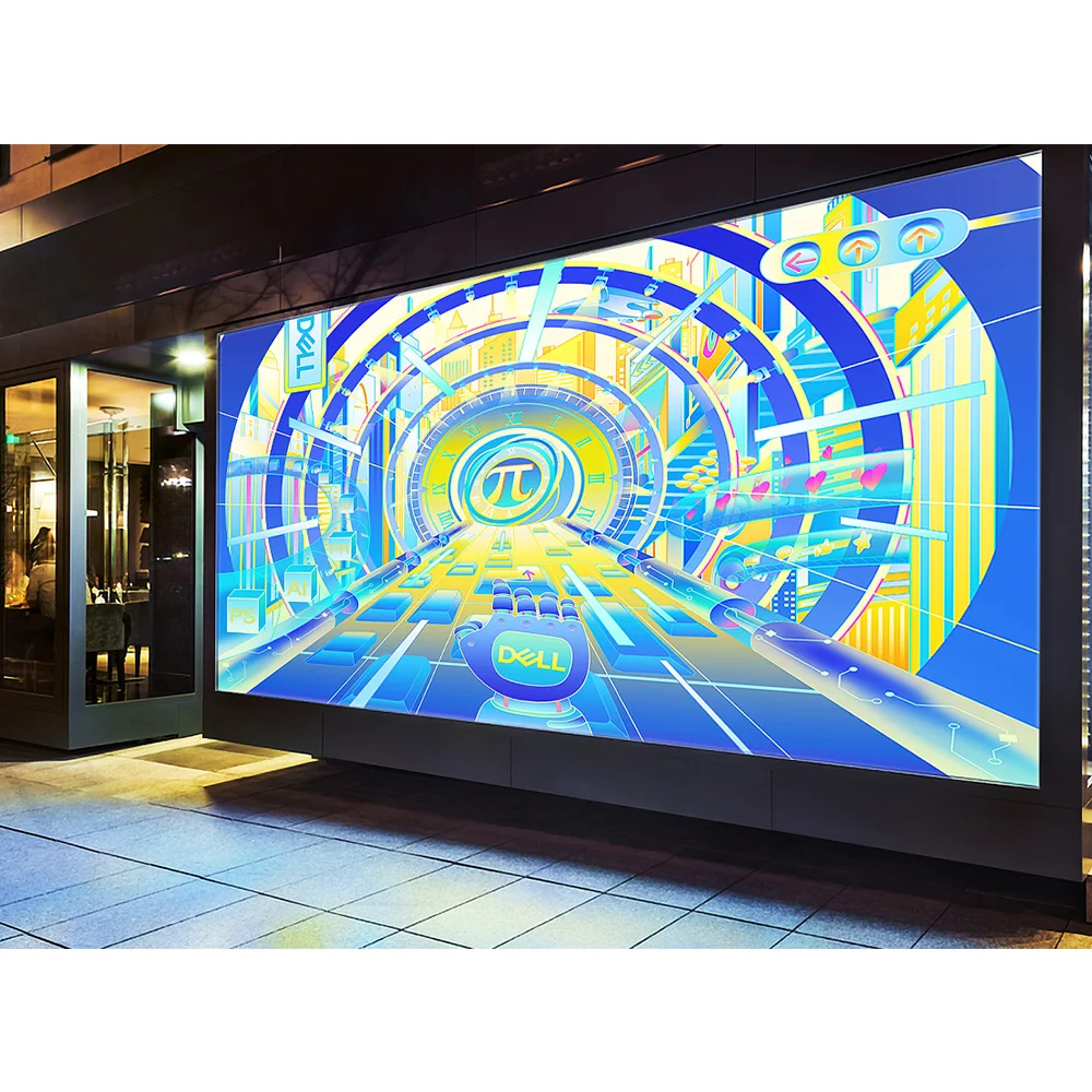
In that context, LED wall panels for events & installations are specified as a repeatable system, not a single product. The visible surface matters, yet the “system” is what keeps a show stable and an installation maintainable. For that reason, the planning mindset should cover cabinets, modules, control, structure, power distribution, and service workflow. Once those parts align, the wall behaves like infrastructure. Afterward, creative teams can treat it like a canvas.
A short field truth helps: most failures are not about “pixels.” Instead, they come from access, cabling, and rushed handover.
What “event-ready” really means on site
Event builds live on a hard schedule. So, the wall must assemble fast, align flat, and stay consistent after repeated rebuilds. At the same time, crews need predictable locks, safe rigging points, and quick module swaps.
In practice, “event-ready” can be summarized into four priorities:
Repeatable mechanics: fast locks, alignment pins, and stable frames
Service workflow: access that matches rehearsal and show timing
Stable signal chain: predictable processing, mapped outputs, and clean routing
Operational resilience: spare strategy, protection, and clear labeling
Even with premium image quality, a wall that takes too long to rebuild becomes a risk. Likewise, an “easy” wall that bands on camera becomes a liability.
Rental vs fixed installation: the difference is the workflow
Rental systems are usually optimized for frequent transport and rebuild cycles. As a result, corner protection, handles, fast locks, and stacking durability become priorities. In addition, touring hardware tends to favor speed over hidden cabling.
Fixed installations often prioritize long-term stability and clean integration. For example, cable trays, tidy power zones, and quiet operation matter more indoors. Also, fixed projects benefit from clearer access planning, because service happens long after commissioning.
On site, the most common mismatch looks simple: a touring cabinet placed into a permanent wall without a service plan. The wall works on day one, yet maintenance becomes disruptive later.
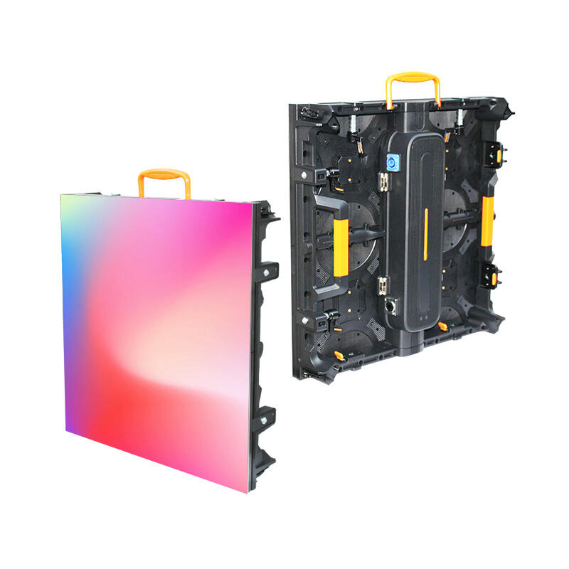
Cabinet mechanics: flatness comes from repeatable alignment
A wall looks “premium” when cabinet planes stay consistent. For that reason, alignment pins, lock tolerance, and frame rigidity matter as much as LED selection. Meanwhile, consistent cabinet batches reduce small seam differences across large surfaces.
Another detail deserves attention: cabinet size affects labor. Smaller formats can help in tight spaces and curve layouts. Larger formats can reduce total connection points and speed up mapping. Still, the “best” cabinet size depends on rigging capacity, access routes, and crew habit.
Touring protection vs weather protection: different failure modes
Outdoor exposure and touring handling are not the same problem. For outdoor sites, sealing strategy and corrosion resistance keep water paths predictable. For touring, impact protection reduces module damage during stacking and transport.
A practical point often gets missed: protection should match the service method. If front service is needed, protective design should still allow safe tool access. If rear service is used, the backstage corridor must remain workable.

Rental-style cabinets often emphasize quick locks, impact protection, and fast handling. LED Display Factory
Pixel pitch and viewing distance: a selection that survives real content
Specs look clean in a chart. Still, real viewing includes angles, ambient light, and content that changes minute to minute. Because of that, pitch selection should start from audience behavior, then confirm camera needs, and finally match budget and structure limits.
A simple decision flow keeps projects grounded:
Define closest meaningful viewing distance (not the average)
Confirm whether cameras will capture the wall (IMAG, broadcast, streaming)
Classify content as text-heavy or video-heavy
Choose cabinet family and service method first
Lock pitch range and validate with test patterns
Finalize processor, mapping, and redundancy plan
This order prevents expensive reversals. It also avoids overbuying pitch while underbuilding infrastructure.
Pixel pitch vs viewing distance reference table
The table below is a planning aid, not a hard rule. Moreover, content type can shift the best pitch by a full class. Note: final selection should be validated against the chosen cabinet series datasheet and the camera test plan.
| Typical application | Closest viewing behavior | Common pitch planning range | Why this range works |
|---|---|---|---|
| Meeting rooms / studios | close viewing, text and UI | P1.2–P2.0 | cleaner text, smoother gradients |
| Exhibitions / retail | mixed distance, brand visuals | P1.8–P2.9 | balanced clarity vs area cost |
| Stages / IMAG | variable distance, camera use | P2.6–P3.9 | efficient scaling, stable audience view |
| Outdoor façades / plazas | far viewing, high ambient light | P3.9–P10+ | visibility, cost control, durability |
Even with a good pitch choice, content can ruin legibility. Dense text and thin lines often fail on large walls. In contrast, LED-friendly design can make a mid-range pitch look sharp.
P2.6 vs P2.9 vs P3.9: a practical stage selection logic
P2.6 often fits stage builds where closer viewing happens at front rows or side seats. It also supports tighter camera pushes when IMAG is central. However, the system cost tends to rise as pitch gets finer, especially at scale.
P2.9 is frequently chosen for balanced event halls. It usually maintains facial detail well at typical audience distances while keeping cabinet count and power planning manageable. In addition, it can be forgiving when stage geometry changes between venues.
P3.9 becomes practical when the audience is mostly farther away and rebuild speed is a priority. Touring crews often like the efficiency and robustness. On camera, though, stability depends heavily on refresh tier, scan strategy, and calibration tools—not pitch alone.
A short “camera reality” line fits here: a wall that looks perfect to the room can still band on lens. That outcome is common when camera testing is postponed.
Indoor meeting rooms: P1.5 / P1.8 selection without over-promising
Meeting rooms and control spaces are usually text-heavy. So, low-brightness uniformity and clean grayscale matter as much as headline brightness. In addition, front service becomes important because deep rear corridors rarely exist in offices.
In many projects, an adjustable brightness range is more valuable than extreme output. Rooms with controlled lighting often operate comfortably in a moderate, tunable range, while still needing enough headroom for daylight spill. Exact values vary by model and environment, so series parameters should confirm the final target.
For narrowing cabinet families and front-service options, the category page Indoor LED Displays (Fine Pitch & Front-Service Options) provides a practical starting point.
Indoor systems often prioritize thin profiles, quiet operation, and front maintenance workflows.
Content style changes the “right pitch” more than expected
Charts and spreadsheets need stable pixel density and clean low-brightness behavior. Meanwhile, cinematic video can look excellent at a slightly larger pitch if distance supports it. Also, brand motion graphics often tolerate larger pitch than small text.
A field pattern shows up repeatedly: when content is designed for LED, the wall can step down one pitch class without losing perceived quality. That shift often saves budget for better processing, redundancy, or structure.
Camera-safe performance: refresh, grayscale, scan, and real checks
This happens all the time: it looks fine to the audience, then bands on camera. The most common “on-lens failure” is not resolution. Instead, it is the interaction between refresh, scan timing, and camera shutter settings.
In other words, camera safety is a workflow, not a single number.
Refresh tiers: treat numbers as filters, then prove them
Refresh rate is often shown as a headline. Still, camera behavior depends on the whole driving chain—driver IC, scan mode, receiving configuration, and processor output. Because of that, refresh tiers work best as a filter that narrows options.
For broadcast-heavy work, many projects target high-refresh classes such as 3,840Hz-class or higher. Some workflows aim even higher, such as 7,680Hz-class, when cameras and close-ups are demanding. Even so, final confirmation should follow the specific cabinet series datasheet and an actual camera test.
A blunt field line helps: a spec sheet never replaces a rehearsal test.
Grayscale and low-brightness behavior: the “premium look” in studios
Grayscale affects gradient smoothness and shadow detail. It also impacts how the wall behaves when dimmed. That matters indoors because rooms often run at comfortable brightness, not maximum brightness.
Uniformity is equally important. Without proper calibration and stable power, one wall section can appear warmer or cooler. As a result, high-end studios often treat calibration as part of acceptance, not an optional extra.
Scan mode and camera shutter: the hidden cause of banding
Scan mode describes how the panel drives LED rows over time. When scan timing collides with camera shutter, artifacts can appear. Often, the wall is blamed first. Yet the root cause is configuration and timing.
In the field, the “mystery flicker” is frequently a configuration mismatch between receiving card settings and the actual module type. When configuration files are managed carefully, this problem becomes rare.
A practical camera test routine for rehearsal days
A repeatable test routine keeps teams calm. It also turns subjective debates into evidence.
Capture wide shots and tight shots, since moiré changes with framing
Record low, mid, and higher brightness scenes, because artifacts can shift
Test common frame rates and shutter ranges used by the production
Keep short recorded clips as acceptance references for later venues
Small changes often solve big problems. For example, a slight camera angle change can reduce moiré. Likewise, content texture adjustments can reduce sensor conflicts.
Engineering that prevents rebuilds: structure, service, power, cooling, EMC
A wall can be visually stunning and still fail as a project deliverable. Most failures are not “display failures.” Instead, they come from structure, access, and infrastructure planning that arrived too late.
Mounting methods: wall-mount, flown, and ground-stacked
Wall-mounted installs depend on a stable backing structure. So, load paths, anchor points, and flatness tolerance should be designed early. Vibration sources matter too, especially near machinery or heavy doors.
Flown walls depend on rigging capacity and safety rules. As a result, load ratings, redundancy, and hardware inspection routines should be documented. Touring workflows benefit from fast rigging bars and repeatable pick points.
Ground-stacked walls rely on a stable base and predictable ballast planning. Outdoor ground stacks add wind considerations, depending on local codes and site exposure.
Front service vs rear service: clearance planning that saves years
Service method should be decided early because it shapes architecture. Front service reduces the need for rear corridors. It also suits meeting rooms and retail walls where space is tight.
Rear service can simplify power box replacement and cable routing. Still, it requires a workable behind-the-wall zone. In many fixed projects, that zone is planned as a service corridor, not a narrow gap. Exact depth depends on cabinet design and safety requirements.
A short reminder fits here: maintenance time is a design input. If fast swaps are expected, access must match that expectation.
Power distribution: circuits, redundancy, and clean routing
Power planning starts with local voltage and available circuits. Next, the wall should be split into zones that match physical sections. That approach simplifies troubleshooting and reduces nuisance trips.
Redundancy can be added in layers. Some projects use dual power feeds for critical sections. Others use N+1 power supplies in distribution boxes. Signal redundancy often follows similar logic with loop topology and dual lines.
Cable routing deserves discipline. Power and signal should be separated where possible. Labels should remain readable in low light. Strain relief should prevent connector fatigue during touring rebuilds.
Heat, noise, and airflow: comfort matters indoors
Indoor meeting rooms often need quiet operation. So, cabinet selection should consider airflow strategy and room HVAC reality. Passive cooling can work well, yet it depends on heat density and ambient temperature.
Outdoor walls face different constraints. Sun, dust, and rain influence thermal behavior. For that reason, cabinet design, sealing strategy, and ventilation approach should match the environment.
Power consumption should be treated as a range, not a fixed value. Average usage depends heavily on content brightness and operating hours. Final estimates should follow the selected cabinet series and the real content profile.
Grounding, surge, and EMC: the invisible reliability layer
Intermittent flicker can be caused by grounding and interference. Long runs can also create signal integrity issues. For that reason, grounding plans, surge protection, and clean routing are part of the display system.
Outdoor projects often include lightning and surge strategies. Large venues can also require attention to EMC when many devices share power and truss routing. In practice, good grounding points and correct shielding prevent most “random” failures.
For weather-rated cabinet families and structure notes, Outdoor LED Displays (Weather-Rated Cabinets & Structure Notes) helps frame the right direction before final engineering review.

Outdoor systems succeed when cabinet mechanics and structure planning match the site conditions.
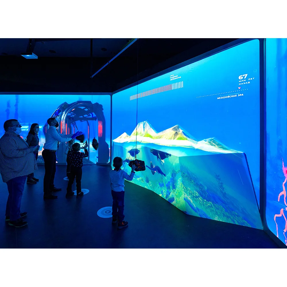
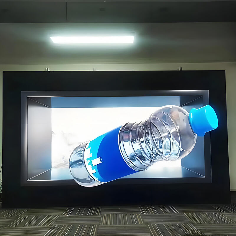
Transparent LED walls: façade integration without guesswork
Transparent LED walls are architectural tools as much as display tools. So, planning should start with the building intent: daylight, visibility, aesthetics, and content style.
A transparent wall usually involves trade-offs. Higher transparency can reduce pixel density. Higher brightness capability can improve daytime readability, yet it can also affect nighttime comfort if dimming strategy is weak. Because of that, the best approach is to plan performance as adjustable ranges and validate with site conditions.
Transparency, brightness, and pitch: balancing the triangle
Many transparent designs fall into a broad transparency range, often around 60–90%, depending on structure and pitch. Still, transparency alone does not guarantee readability. Content must be bold, and viewing distance must support the chosen pitch class.
Daylight is the hardest constraint. Glass façades can be extremely bright in daytime. At night, the same wall can feel overly intense without controlled dimming. For that reason, a wide dimming range and stable low-brightness behavior matter.
Installation methods: mullions, hanging points, and frame alignment
Transparent cabinets often mount to mullion-aligned frames. As a result, measurement accuracy becomes critical. Cable routing must also respect the building appearance, because visible clutter defeats the purpose.
Hanging installs are common in atriums and showrooms. Even then, load paths and safety factors should be documented. Lightweight cabinet design can reduce reinforcement needs in retrofit projects.
Alignment mistakes show up quickly. A small twist becomes a visible gap. Therefore, frame flatness and consistent mounting points matter.
Content rules that make transparent walls look “right”
Transparent walls reward simple content. Large typography, strong contrast, and clear motion usually read well. Dense text tends to fail, even with a good pitch.
A practical guideline helps teams: design as if the background always remains visible. That mindset improves readability without hardware changes.
Transparent systems rely on frame alignment and clean routing to stay “architectural.”
Control chain and ecosystem choices: stability first, brand second
A video wall is only as stable as its control chain. So, control planning should cover signal sources, mapping, redundancy, and operational monitoring.
A common chain looks simple: source → processor/scaler → sending → receiving → modules. The reliability, however, comes from details like EDID handling, cable length, and consistent configuration management.
Processor and mapping: the daily operator experience
Processors handle scaling, switching, and mapping. In event workflows, they also stabilize quick changes between laptops, cameras, and playback servers. In installations, they may support scheduling and remote monitoring.
Misconfigured scaling is a classic “looks soft” problem. Meanwhile, poor EDID negotiation is a classic “no signal” problem. Both issues are easier to prevent than to chase during a rehearsal.
NovaStar / Colorlight / Brompton / Barco: a selection logic, not a name list
These ecosystems appear often in the industry. Still, the practical approach is to choose based on workflow and support habits, then confirm actual supply and project practice.
For live events and broadcast, priority often goes to camera behavior, calibration tools, stable switching, and repeatable profiles.
For fixed installs and multi-site operations, priority often shifts to remote monitoring, maintenance workflow, and long-term configuration consistency.
In all cases, the final ecosystem should match the project’s operational plan and the cabinet series compatibility. Brand choice is less important than predictable support and documentation.
Redundancy and topology: simple patterns that prevent downtime
Redundancy does not need to be complicated. It needs to be consistent.
Use loop topology or dual lines where a single failure would be disruptive
Keep spare sending/receiving components aligned with the installed ecosystem
Label every line and document the topology in a one-page map
Separate power and signal paths to reduce cross-interference
A short field line fits again: many “screen problems” are actually signal problems. Checking source, processor output, and cable integrity should happen before replacing modules.
LED wall vs projection vs LCD video wall: a practical comparison
Decision makers often compare display technologies. That comparison becomes clearer when maintenance and environment are included, not only picture quality.
| Technology | Best strengths | Common limits | Maintenance reality | Typical fit |
|---|---|---|---|---|
| LED wall system | seamless scaling, high impact, flexible shapes | upfront system planning | modular repairs, needs access plan | events, stages, premium installs |
| Projection | low initial hardware in some cases | ambient light sensitivity | lamps/lasers and alignment | dark rooms, temporary setups |
| LCD video wall | sharp UI, consistent panels | bezels, size limitations | panel replacement and calibration | control rooms, corporate lobbies |
In bright venues, projection struggles. In bezel-sensitive designs, LCD walls may not fit. LED walls, in contrast, demand stronger engineering planning, yet they scale well once infrastructure is right.
Factory quote planning: what drives cost, and what to prepare
A factory quote becomes accurate when inputs are clear. So, quote preparation should be treated as an engineering step, not a formality.
When comparing LED video wall manufacturers, the most useful comparison is not only price per square meter. Instead, it is the completeness of scope: cabinet family, control chain, structure plan, distribution, spares, packing, shipping, commissioning, and warranty terms.
Quote drivers that change totals the most
Several variables move cost quickly:
Pixel pitch class and LED package type
Cabinet mechanics, material, and service method
Processor scope and redundancy requirements
Structure method and site safety constraints
Logistics, packing method, and schedule window
Spare strategy and warranty preference
A common cost surprise is structure. Another surprise is “format creep,” when input requirements change late and extra processing or conversion is needed.
Quote preparation checklist (copy-friendly)
Provide the items below to reduce back-and-forth and tighten pricing accuracy.
| Quote input | What to provide | Why it matters |
|---|---|---|
| Use case | indoor / outdoor / rental / transparent | defines cabinet family and protection |
| Closest viewing distance | approximate range, audience flow | drives pitch planning and resolution |
| Content type | text-heavy / video-heavy / IMAG | affects pitch, processing, calibration |
| Target size | width × height or target area | defines cabinet count and mapping |
| Mounting method | wall-mount / flown / ground-stack | changes structure and safety scope |
| Service method | front or rear + site constraints | sets access and cabinet selection |
| Control method | synchronous / asynchronous + inputs | defines processor and sending needs |
| Power | local voltage + available circuits | drives distribution and redundancy |
| Delivery scope | screen only / include structure / include install | prevents hidden cost items |
| Spares & warranty | spares ratio preference, warranty terms | defines operational plan |
| Logistics | destination + timeline window | influences packing and shipping |
After submission through the site inquiry form or contact page, an efficient factory process usually responds with multiple configuration tiers.
What a quote output typically includes
A usable quote package is more than a single line price. It usually includes three tiers to match different priorities. One tier often focuses on budget efficiency. Another tier targets balanced performance and stability. A third tier targets demanding camera work and premium uniformity.
Each tier normally lists cabinet specifications, quantity, mapping notes, and a recommended spares set. It also includes control components such as processor, sending, receiving, and typical accessories. In addition, structure guidance and power estimates are often provided as ranges, because content and operating hours strongly affect averages. Final values should always follow the selected cabinet series datasheet and the confirmed project scope.
Hidden costs and “scope gaps” worth naming early
Scope gaps cause the most frustration. Naming them early reduces rework and rushed freight.
| Scope area | What often gets missed | Why it matters |
|---|---|---|
| Structure | reinforcement, wind planning, access platforms | late changes are costly |
| Power | circuit count, phase balance, redundancy | trips and downtime risks |
| Signal | long runs, format conversion, fiber | intermittent issues appear late |
| Commissioning | calibration, camera tests, acceptance clips | prevents disputes later |
| Spares | modules, PSU, receiving cards, cables | avoids “one fault stops all” |
| Logistics | crates, handling limits, schedule window | controls damage and delays |
A simple philosophy helps: if the scope is unclear, the project cost appears later anyway.
Spare parts guidance for events and long-term operation
Spare planning keeps downtime manageable. It also protects schedules when a single part fails.
Common spares include modules, a small number of power supplies, receiving cards, and key cables/connectors. For touring builds, corner protectors and fasteners also matter because mechanical wear is frequent. The final spare ratio depends on wall size, rebuild frequency, and service policy.
Avoid-rework checklist: 10 common reasons projects get rebuilt
Most rebuilds are preventable. Still, they happen because small assumptions stack up. Each point below reflects a real pattern seen in event and installation workflows.
Service access was assumed, not designed.
Access often becomes an afterthought when drawings focus only on the visible wall. Later, a simple module swap turns into partial dismantling. Over time, maintenance becomes disruptive and expensive.Rear clearance was too tight to work safely.
A narrow gap can exist “on paper,” yet tools and hands still need room. Power boxes and connectors also need reach and visibility. When clearance is insufficient, repairs get delayed and mistakes increase.The backing structure was not flat enough for seamless splicing.
Minor twists create visible seams and uneven reflections. Crews then spend hours shimming every rebuild. The wall can still function, yet the look never reaches its potential.Power circuits were underestimated during early planning.
Temporary extensions appear, and reliability drops quickly. During brighter scenes, nuisance trips become more common. In venues with shared loads, the problem can spread beyond the wall.Signal routing was treated like generic Ethernet cabling.
Long copper runs and noisy pathways increase intermittent artifacts. The wall might pass basic checks, then fail during busy rehearsals. Later, fiber or better routing becomes a retrofit, not a plan.Grounding and surge strategy were skipped.
Intermittent flicker often appears after weather changes or power events. The wall is blamed first, while infrastructure remains the root cause. Proper grounding points and surge planning reduce these “random” failures.Configuration files were not controlled across rebuilds.
A receiving configuration mismatch can cause banding, flicker, or color inconsistency. Rebuild pressure makes mistakes more likely. A disciplined file and labeling process prevents most of these issues.Mixed cabinet batches introduced color or seam differences.
Large walls reveal small variations quickly. Even when modules meet spec, visual differences can appear across batches. Consistent batching and calibration planning help keep the wall uniform.Camera testing was delayed until the last moment.
The wall can look stable to human eyes, so testing is postponed. Then, close-ups show banding or moiré. Fixing the issue becomes harder when rehearsal time is already gone.Scope language was vague, so hidden costs arrived late.
Structure, distribution, commissioning, and spares can be excluded without clear wording. Budget then grows after procurement, not before it. Clear scope statements prevent “screen only” misunderstandings.
Three reference solutions: practical patterns for planning
The examples below show common planning structures. Exact specifications depend on cabinet series, environment, and the final engineering review.
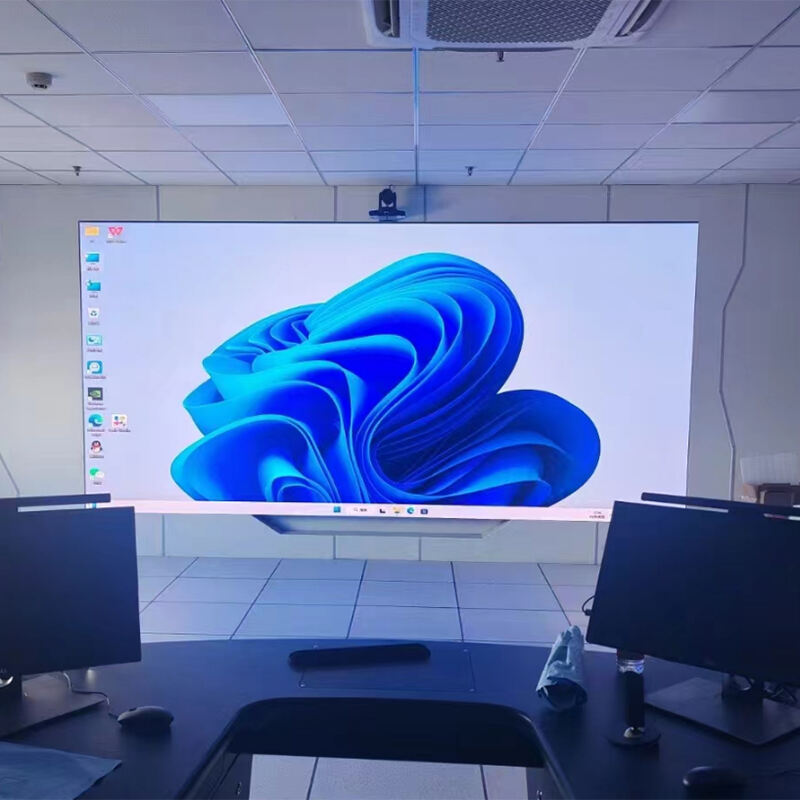
Example A: Boardroom LED wall with heavy text and video calls
A boardroom wall typically targets a wide aspect ratio and consistent low-brightness performance. For instance, a 5–8 meter class width with a 2.5–4 meter class height is common in medium and large rooms, depending on seating layout. In that setting, a fine-pitch range such as P1.2–P1.8 class often supports legible text and clean UI.
Brightness planning usually focuses on comfort and controllability. Many rooms operate within a moderate adjustable range under controlled lighting, while still needing headroom for daylight spill from windows. Because the wall is viewed at close distances, uniformity and grayscale stability at lower brightness become important acceptance factors.
Control design is often synchronous, supporting laptop sources, conferencing codecs, and presentation switchers. A processor with stable scaling and reliable EDID handling reduces “no signal” surprises during meetings. On the structural side, front service is frequently chosen because rear corridors are rare. As a result, the mounting frame should allow safe tool access and predictable module removal. Finally, commissioning typically includes seam checks, uniformity calibration, and a short camera verification for common shutter settings used in hybrid meetings.
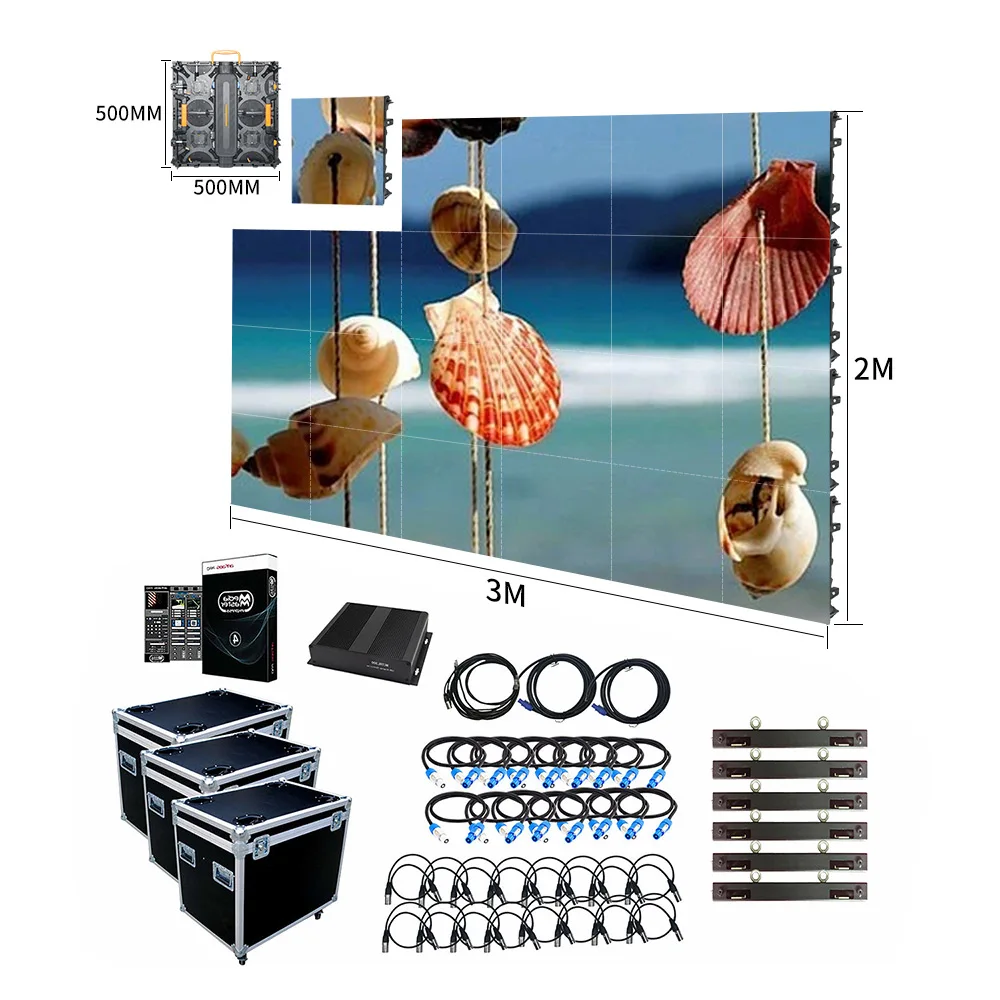
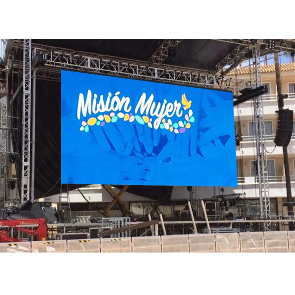
Example B: Touring stage wall for IMAG with fast rebuild cycles
Touring builds prioritize speed, repeatability, and camera stability. A common stage wall might sit in a 10–16 meter class width and 5–8 meter class height, depending on venue capacity and rigging limits. In that workflow, pitch often falls into a P2.6–P3.9 class range, since audience distance varies and rebuild speed matters. Camera behavior can still push the choice toward finer pitch, especially when tight shots are frequent.
Refresh planning should follow a workflow approach. High-refresh classes (often 3,840Hz-class or above, model-dependent) are frequently selected for broadcast comfort. Even then, scan mode, receiving configuration, and processor mapping remain critical. A practical rehearsal routine—wide and tight shots at typical shutter ranges—reduces last-minute surprises.
Structural planning usually uses flown truss or reinforced ground stacks. Rigging hardware must be documented, inspected, and aligned to safety rules. Power distribution is typically zoned by wall sections, with clear labeling for rapid troubleshooting. Spares matter more than many expect in touring. A workable kit often includes spare modules, a few power supplies, receiving cards, and the connectors most likely to suffer wear during transport. When these pieces are planned, rebuild cycles stay predictable instead of stressful.
Example C: Retail glass façade with transparent display and daylight constraints
A transparent installation often spans a wide window bay and must look architectural when off. A typical façade coverage might be 4–12 meter class width, sometimes across multiple window sections. Pitch selection balances readability with transparency. Larger pitch generally improves transparency, while smaller pitch improves detail. Because glass environments are bright, daytime readability becomes a core constraint.
Brightness strategy should be adjustable and site-aware. Glass façades can be extremely bright in daytime and visually sensitive at night. So, the system should support stable dimming across a wide operating range, with final values confirmed by the cabinet series datasheet and the site lighting reality.
Installation frequently uses mullion-aligned frames or hanging points, depending on building structure. Measurement accuracy and alignment are critical, because visible gaps defeat the purpose. Cable routing must also remain clean and discreet. Control design often includes scheduled playback, remote monitoring, and stable content mapping across segments. For content, bold visuals and large typography typically outperform dense text. When content respects the “background always visible” rule, the wall looks intentional instead of cluttered.
FAQ: selection questions that appear in real events and real installs
1) What is the difference between rental LED screens and fixed installation screens?
Rental systems are built around repeated transport and rebuild cycles. So, cabinets often emphasize quick locks, handles, corner protection, and fast stacking workflows. Fixed systems, in contrast, tend to prioritize clean cable routing, long-term stability, and predictable service corridors. Both can display video well, yet the project risk shifts: rental risk is rebuild wear and alignment drift, while fixed risk is access planning that was never designed.
2) How should P2.6, P2.9, and P3.9 be chosen for an event hall?
The first input should be the closest meaningful viewing distance and whether IMAG is central. P2.6 often supports closer viewing and tighter camera pushes. P2.9 commonly balances clarity and scale cost for mixed distances. P3.9 is frequently chosen when audiences are farther and rebuild speed matters. After pitch, camera behavior should be validated with refresh tier, scan strategy, and a rehearsal test.
3) Why can a wall look fine to human eyes but fail on camera?
Cameras sample light based on shutter timing and sensor readout. LED walls drive light based on refresh and scan timing. When timing patterns collide, banding or flicker can appear on footage even if the room view looks stable. Because of that, camera safety should be proven by testing with the actual cameras, common shutter ranges, and brightness levels used in rehearsal.
4) How should refresh rate be discussed without relying on one number?
Refresh values are useful as a filter, but they do not guarantee camera comfort alone. The full chain—driver IC, scan mode, receiving configuration, and processor output—shapes the final result. High refresh classes, such as 3,840Hz-class or higher (model-dependent), are often selected for broadcast workflows. Even so, the strongest proof remains a recorded rehearsal test under real camera settings.
5) What causes moiré, and can pitch alone prevent it?
Moiré often appears when a camera sensor grid conflicts with the LED pixel grid. Pitch influences the risk, yet lens choice, focus, distance, and angle also matter. Content with fine repeating patterns can trigger moiré even on strong hardware. Practical mitigation often includes camera angle adjustment, focus changes, or content texture changes, alongside selecting a pitch that matches typical viewing distances.
6) How should indoor meeting room brightness be planned without over-specifying?
Meeting rooms usually benefit from comfortable, adjustable brightness rather than extreme output. Ambient lighting, window exposure, and wall placement shape the real need. Many rooms operate within a moderate adjustable range when lighting is controlled, yet still need headroom for brighter daytime conditions. Final brightness targets should follow the chosen cabinet series datasheet and be verified during commissioning.
7) What does “front service” change in a real installation?
Front service allows module or component access from the viewing side. That approach can remove the need for a rear corridor, which is helpful in offices and retail. Still, front service requires the correct cabinet design and safe tool access. The mounting frame must also support predictable module removal without damaging surrounding finishes. Planning front service early prevents later rebuilds caused by missing access.
8) How much rear clearance should be reserved for rear service?
Rear service requires a workable access zone rather than a narrow gap. The exact clearance depends on cabinet depth, connector layout, and safety requirements. In many fixed installations, the behind-wall zone is treated as a corridor with lighting, stable footing, and cable trays. Final clearance should be confirmed using the selected cabinet design and the service workflow expected during operation.
9) What role do power distribution and phase balance play?
Power planning affects stability and uptime. Large walls benefit from zoning that matches physical sections, which helps troubleshooting and reduces nuisance trips. Phase balance can reduce stress on circuits, depending on the electrical system. Redundancy can be added via dual feeds or N+1 strategies, based on project scope. Clean routing and labeling improve safety and maintenance speed long after handover.
10) How should cooling and noise be considered for indoor installations?
Indoor spaces often demand quiet operation, especially in meeting rooms and studios. Cabinet airflow strategy and room HVAC should be considered together. Passive cooling can work, yet heat density and ambient temperature must be respected. Content brightness profile also affects average heat. Planning power as ranges, tied to real content, avoids underestimating heat and noise requirements.
11) Why do EMC and grounding show up in “display problems”?
EMC and grounding issues can cause intermittent artifacts that look like display faults. Long cable runs, shared power with noisy devices, and poor grounding points can create instability. Surge planning also matters in outdoor and large venues. Practical measures—good grounding, correct shielding, separated routing, and documented topology—prevent many “random flickers” that are otherwise hard to diagnose.
12) How should transparent LED screens be evaluated for glass façades?
Evaluation should start with architectural goals: visibility through glass, daytime readability, and clean appearance. Transparency, pitch, and brightness capability form a trade-off triangle. Content style matters too, because bold visuals outperform dense text on transparent structures. Installation method should align with mullions or hanging points, and routing should stay discreet. Final performance should be validated against the cabinet series datasheet and the site environment.
13) What makes a quote “accurate” instead of “ballpark”?
Accuracy comes from clear inputs: use case, target size, viewing distance, content type, mounting method, service method, control approach, and delivery scope. Sketches and site photos also reduce uncertainty. When scope is defined, pricing reflects real structure, distribution, and commissioning needs. When scope is vague, hidden costs usually appear later through rework, extra accessories, or rushed logistics.
14) What does a professional quote package usually include?
A professional package often offers tiered configurations—value, balanced, and higher-spec—so trade-offs are visible. It typically includes a bill of materials, cabinet count, mapping notes, control components, and a recommended spares set. Structure guidance and power estimates may be provided as ranges, since content and operating hours affect averages. Warranty terms, packing method, and schedule notes also help align expectations.
15) How should spares be planned for event use versus fixed installs?
Event workflows often benefit from more mechanical and connector spares, because handling wear is frequent. Modules, power supplies, receiving cards, and key cables are common choices. Fixed installs may focus more on keeping a small set of critical electronics and modules for quick restoration. In both cases, spares planning should match wall scale and operational tolerance for downtime.
16) What is the most common reason projects miss schedule during installation?
The most common reason is late discovery of infrastructure constraints: missing circuits, unclear routing, insufficient access space, or structure that needs reinforcement. These issues create cascading delays because they affect multiple trades. Early coordination between display design and building or stage design reduces these late surprises and keeps commissioning predictable.
17) How should “high brightness” claims be handled responsibly?
Brightness capability matters, especially outdoors and behind glass. Still, the practical target should be framed as adjustable ranges based on ambient light and usage hours. Over-specifying without site validation can cause glare at night or wasted power capacity. Final targets should follow the chosen cabinet series datasheet and be confirmed during commissioning with real content.
18) What is a reliable acceptance method for events and installations?
Acceptance should combine visual checks and workflow checks. Visual checks include uniformity, seam inspection, and test patterns across brightness ranges. Workflow checks include camera tests for event builds, input switching stability, and service access verification. Recorded clips and documented configuration files create a clean handover baseline that supports future rebuilds and maintenance.
Summary and next steps
Events reward speed and stability. Installations reward serviceability and clean integration. When both goals are treated as system requirements, the result looks better and behaves better. That means cabinet mechanics, access workflow, power distribution, signal topology, and commissioning routines deserve the same attention as pitch selection.
When it is time to request a quote, LED wall panels for events & installations can be scoped accurately by using the checklist and the test routines above. Clear scope reduces hidden costs, while disciplined testing reduces last-minute surprises.
Three actionable recommendations
Lock the workflow first: decide rental vs fixed, then choose cabinet family and service method.
Prove camera behavior early: record rehearsal clips under real shutter ranges and brightness levels.
Design service access on paper: decide front or rear service, then reserve the clearance and tool path before the structure is built.