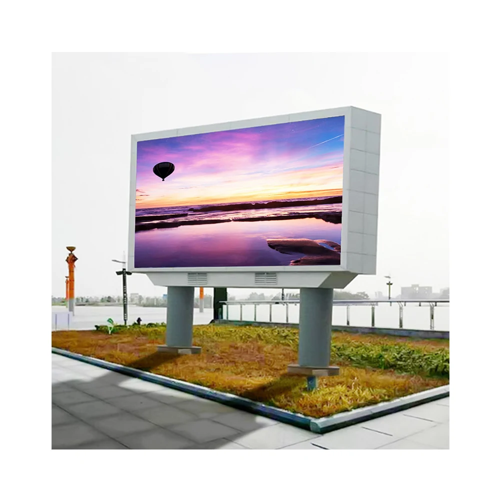
An LED display can work perfectly during workshop testing and still develop interference after installation. A section may flicker when nearby equipment starts, communication may become unstable only with one source connected, or visual artifacts may appear after the final cable route and supporting structure are in place.
When that happens, the most useful question is not simply, “Is this an EMC problem?” It is what changed between the last stable condition and the condition in which the problem appears. In a custom LED screen project, that change may involve the cabinets, power relationships, control equipment, an external source, cable routing, shielding transitions or another system introduced during installation.
This approach matters because EMI troubleshooting quickly becomes unreliable when several things are changed at once. The goal is to narrow the problem logically, preserve useful evidence and give the right engineering team enough information to investigate the next boundary.
A useful starting point: compare the last known stable setup with the setup in which the interference appears. Look for the equipment, connection, cable route, power relationship or installation condition that changed between them.
Why EMI Problems Often Appear Only After Installation
“The screen is flickering” describes what the user sees, but it does not explain why it is happening. Before focusing on shielding, grounding or signal isolation, it helps to understand the electrical and physical environment around the display.
A screen installed near switching equipment, motors, building controls, broadcast systems or several AV devices has more electrical relationships than a standalone test screen. That does not mean nearby equipment is automatically responsible. It becomes relevant only when its operating state has a repeatable relationship with the screen behaviour.
The same applies to cable routing. A signal or power cable may pass through an electrically busy area, but the route alone does not prove that interference is being coupled into the display. A stronger clue is a repeatable difference between two otherwise similar conditions.
Before troubleshooting, map these four relationships
01Nearby equipment
What systems operate close to the screen, control equipment or relevant cable routes?
02Power relationships
Which systems share power infrastructure and which are supplied separately?
03Control interfaces
Where do sources, processors, sending equipment, receiving equipment and the screen connect?
04Physical installation
How do cabinets, support structure, cable entry points and service areas come together on site?
It also helps to know who controls each part of the installation. The LED supplier may be responsible for display-side interfaces and drawings. The AV integrator may manage the source and processor. The electrical contractor may control site distribution, while another engineering team may be responsible for equipment operating nearby.
Making those boundaries clear prevents the investigation from becoming a series of unrelated component replacements.
Where Shielding Problems Can Enter an LED Display System
Shielding is often discussed as if it were a single component choice: use a shielded cable, add a metal enclosure or introduce conductive material. In practice, shielding works as part of a complete path. What matters is where the shielded region starts, where it ends and what happens when power or signals cross that boundary.
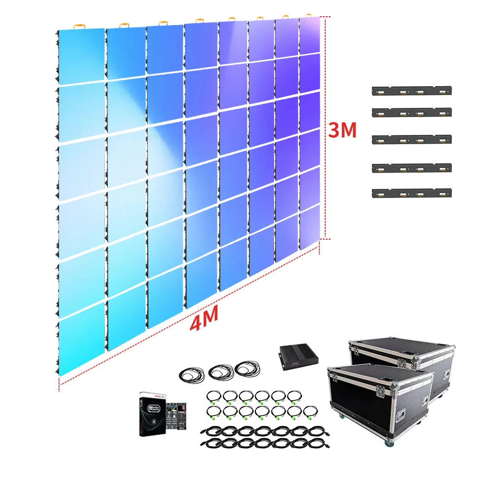
In an installed LED display, that review can include cabinet construction, cable shields, connectors, cable-entry areas, interface transitions and the supporting structure. When multiple LED screen panels are assembled into a larger display, the finished installation should be considered as a system rather than assuming that one isolated cabinet represents every final interface.
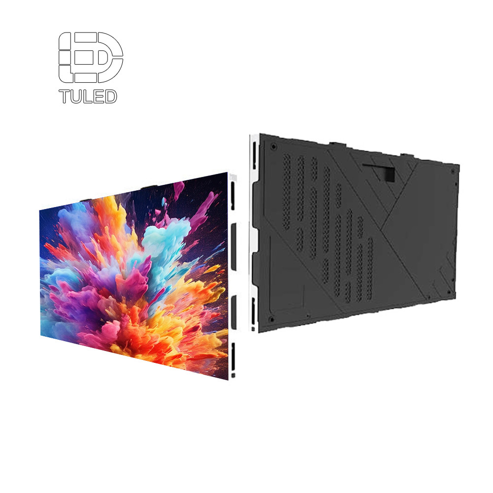
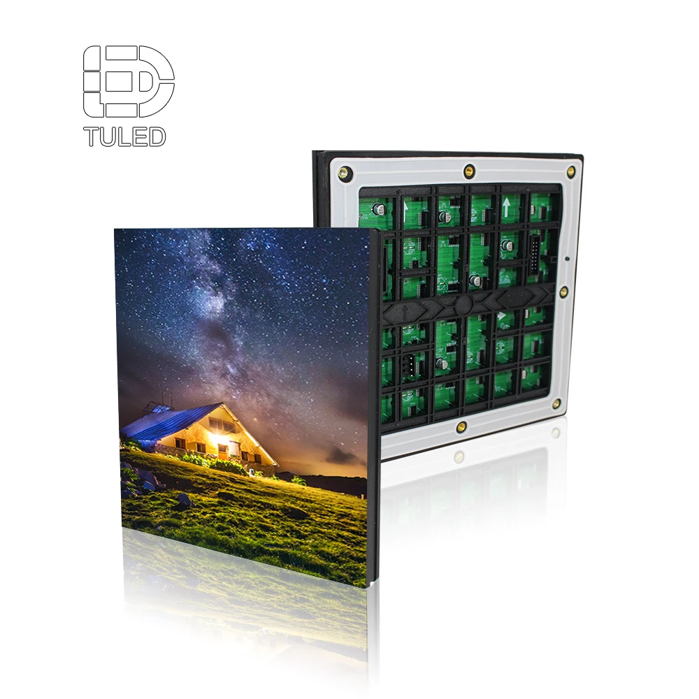
The cabinet view helps show where several EMC-relevant relationships meet: power and signal cable entry, the control card, power supply and the physical arrangement of components inside the panel. It is shown here to illustrate interface planning rather than to imply a specific EMC rating.
What is worth checking when shielding is suspected?
Boundary
Which equipment or cable path sits inside or outside the intended shielded region?
Transition
Where does a cable, connector or interface move between different physical or electrical environments?
Continuity
Are there connectors, adapters or structural transitions that behave differently from the rest of the path?
Evidence
Does changing the suspected interface or exposure condition produce a repeatable change in the symptom?
If a display is stable until one external connection is introduced, that interface deserves more attention than an unrelated cabinet surface. If the problem begins only after the final cable route is installed, the difference between the temporary test route and the permanent route becomes useful evidence.
Shielding performance figures should come from verified project specifications or test records. Numbers taken from an unrelated installation can create more confusion than they solve.
When a Ground Loop Is Worth Investigating
Ground loops are often blamed for unexplained noise, flicker or unstable communication because several different electrical problems can look similar from the screen side.
A better starting point is to ask whether interconnected equipment creates more than one conductive relationship through power references, signal interfaces, cable shields or supporting structures. Equipment supplied from different distribution points, third-party control equipment and conductive mounting structures may all be relevant, but none of them proves that a ground loop is the cause.
For example, imagine a screen that works normally with a local source. A second externally powered system is connected and an intermittent artifact begins. At that stage, the strongest evidence is not “the installation has a ground loop.” It is that adding one new system boundary changed the behaviour.
That observation can then be shared with the electrical, AV and display teams, who can review the power and signal relationships using drawings and controlled comparisons rather than working from an assumption.
Keep safety separate from troubleshooting shortcuts
EMI investigation should not involve casually disconnecting protective earth conductors, bypassing safety provisions or altering mains infrastructure as an informal test. Protective grounding and site electrical distribution should remain with qualified personnel working to the applicable project requirements.
A supplier can usually begin reviewing the problem without any improvised electrical modification. A wiring diagram, installation photos and a record of which connection or operating state changes the symptom provide a much better starting point.
When Signal Isolation Becomes Relevant
Signal isolation becomes worth discussing when troubleshooting points toward an electrical relationship between interconnected systems. It should not be treated as a standard accessory to add whenever EMI is suspected.
Start by tracing the interface chain involved when the problem occurs. A typical LED display project may include a media source, processor or sending equipment, receiving equipment and the display itself. The important question is where separately powered or separately managed equipment becomes electrically interconnected.
Source Media or AV source
Identify which source is connected when the symptom occurs.
Control Processor / sending side
Confirm the interface entering the LED control system.
Display Receiving side
Identify where the control path enters the screen cabinets.
Compare Change one condition
Observe whether the symptom changes when one relevant interface condition changes.
If the interference disappears when one external interface is removed, that does not automatically mean an isolator is required. It does, however, identify an interface worth investigating more closely.
The next step is to determine whether the interaction belongs to the source side, control equipment, display side or another shared electrical relationship. Processor, sending-card and receiving-card coordination can also be reviewed through the site's LED display control accessories.
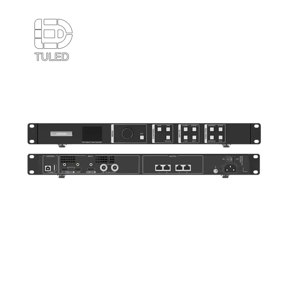
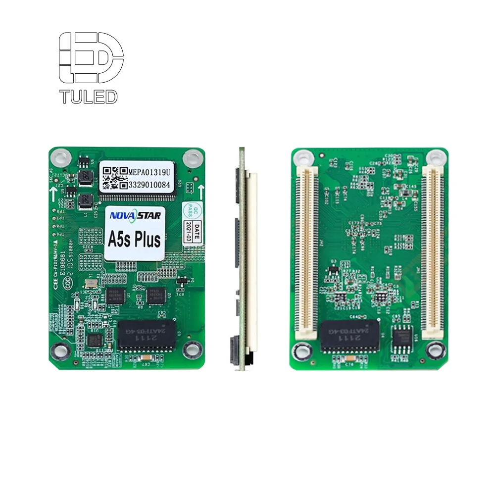
The examples below are useful for understanding where those control-system interfaces sit. They are not isolation devices, and showing them here does not imply that either product causes or fixes an EMI problem.
Processor-side reference
Novastar CMS260 Video Processor
The front-and-rear view can help document which external source and processor interfaces are present in the affected configuration. It is useful for mapping the connection path, not for assuming the processor is the source of interference.
A receiving card sits on the display side of the control path. Identifying where the processor or sending side hands data into receiving equipment helps define which interface should be documented and compared.
Signal isolation makes more sense after controlled troubleshooting has shown that a particular interface or conductive relationship is relevant. Adding isolation first and looking for a reason afterward makes the diagnosis less reliable.
How to Narrow Down the Source of the Interference
One of the easiest ways to lose useful diagnostic information is to change several things at once. Replacing a cable, changing the source, moving the processor and altering another connection in the same test may make the problem disappear, but it leaves no clear explanation of what actually mattered.
A more useful approach is to describe the problem clearly, change one meaningful condition, compare the result and keep a record.
1
Define the symptom
Record exactly what the screen does and when it happens.
2
Change one variable
Choose one relevant and safely controllable condition.
3
Compare the result
Repeat the same operating condition and see whether the behaviour changes.
4
Keep the evidence
Record the condition, result and who should review the next boundary.
Describe the symptom precisely
“Interference” is too broad for a supplier or integrator to work from. Record whether the display shows transient artifacts, periodic flicker, signal loss, instability in one area or a wider control problem.
Also note whether the whole screen is affected and whether the problem appears when another device starts, stops or changes operating state. A problem that occurs in the same sequence repeatedly gives engineers a much stronger reference than one described simply as “random.”
Change one thing that answers a real question
A useful comparison starts with a hypothesis. If an external source interface is suspected, compare the same display condition with and without that interface where doing so is safe and appropriate. If the problem appeared only after final cable routing, compare what changed between the temporary test route and the installed route.
The purpose is not to disconnect equipment until the problem disappears. It is to learn whether one defined boundary has a repeatable relationship with the symptom.
A useful troubleshooting record
“Artifact appears whenever equipment X enters operating state Y. With interface Z removed, the display remains stable during repeated tests of the same condition. After interface Z is restored, the artifact returns under the same operating state.”
This still does not prove the electrical mechanism, but it gives the next engineering team a repeatable relationship that can be investigated.
Keep the tests that did not change anything
A test that produces no change is still useful because it removes one suspected relationship from the investigation.
In a project involving several contractors, a short troubleshooting log also prevents another team from repeating the same unsuccessful checks days later. Useful records include the date, connected equipment, nearby equipment state, symptom, variable changed, result and the team responsible for the next review.
Photos and short videos can make those records much easier to understand remotely.
What Information Helps Diagnose the Problem Faster
An EMI-sensitive enquiry usually needs more than the dimensions of the screen. The supplier needs enough context to understand how the display connects to the rest of the installation.
For a new project, this information can expose interface questions before installation. For an existing problem, it helps distinguish the permanent design from the particular condition that triggers the interference.
Screen width and height
Screen quantity
Site and installation photos
Wiring or control diagram
Display power source
Signal source
Processor or control-equipment information
Cable-routing information
Nearby equipment associated with the symptom
Installation country
Observed EMI behaviour and trigger condition
Project or troubleshooting timeline
For an intermittent problem, a site video is much more useful when it captures the trigger as well as the screen. A close-up confirms what the display is doing; a wider recording that shows another system operating at the same moment gives the engineering team additional context.
The wiring diagram does not need to be a polished construction drawing for an initial review. What matters is that the signal source, control equipment, display and relevant power relationships can be followed clearly enough to understand how the systems connect.
When to Bring the LED Supplier Into the Investigation
Factory support becomes more effective once a vague complaint has been turned into a documented condition. The supplier can then focus on the parts that belong to the display system, including cabinet interfaces, control-equipment relationships, relevant drawings and previous troubleshooting results.
For a project still in design, these relationships are easier to review before the screen is surrounded by final finishes, permanent cable routes and third-party systems. Not every EMC problem can be predicted from drawings, but avoidable uncertainty about the interfaces can often be removed early.
For a display that is already installed, the most useful information is usually the difference between the condition in which the screen works and the condition in which the problem appears.
Give the supplier evidence, not just a symptom
Instead of sending only “the screen has interference,” include the wiring relationship, site photos, symptom video, operating condition, test history and the specific connection or system boundary that appears to change the behaviour. This allows display-side checks to be coordinated around evidence rather than unrelated component replacements.
If the display works normally until a third-party system is introduced, the shared interface may need input from both teams. If the symptom remains after those external relationships have been removed from the comparison, the investigation can move deeper into the display-side configuration.
Common EMI Symptoms and What to Check Next
The table below is not intended to turn a symptom into an automatic diagnosis. Its purpose is to show which relationship is worth investigating next and what evidence can make that investigation more useful.
Observed Symptom
What to Look At
Useful Evidence
What to Do Next
Visual artifact appears when nearby equipment starts
Relationship between the display, connected interfaces and the equipment operating nearby
Video, equipment operating state, timing and a basic system diagram
Repeat the same condition while changing one relevant interface variable
Control becomes unstable only after final installation
Installation-specific interface, cable route or electrical relationship
Final routing photos, control diagram and comparison with the previous stable setup
Identify exactly what changed between temporary testing and final installation
Problem appears only with one external source
Source-to-control-system interface
Source identification, connection path and repeatable before-and-after results
Review the shared interface before replacing unrelated display hardware
One configuration is stable and another is not
The connection, device or electrical relationship introduced by the changed configuration
Exact configuration difference and repeated comparison results
Assign the changed boundary to the appropriate display, AV or electrical team
The problem cannot be reproduced reliably
The trigger condition has not yet been isolated
Time, nearby equipment states, source condition, photos, video and previous test history
Build a repeatable symptom profile before replacing components
A ground loop is suspected
Multiple interconnected power, signal and structural relationships
Wiring diagram, equipment power relationships and affected interfaces
Have the appropriate qualified teams review the relationships before naming the cause
Important: these are investigation directions, not confirmed root causes.
Frequently Asked Questions
What information should I send when an LED screen has EMI problems?
Provide the screen size and quantity, installation photos, wiring or control diagram, power and signal sources, cable routing, relevant processor or control-equipment information, nearby equipment and a precise description of when the problem appears or disappears. A repeatable trigger is especially useful.
How do I know whether a ground loop is actually causing the problem?
Start by mapping the electrical and signal relationships rather than naming the cause from the symptom. Identify which systems are interconnected, how they are powered and whether changing one interface repeatedly changes the screen behaviour. A ground loop should remain a hypothesis until the relevant engineering teams have evidence supporting it.
When should signal isolation be considered?
Signal isolation is worth reviewing when controlled troubleshooting repeatedly points to a particular interface between systems as a meaningful electrical boundary. It should follow an assessment of that interface rather than being added automatically whenever interference is reported.
Have the Installation Details Ready Before the Technical Review
If you are planning an EMC-sensitive LED display installation or troubleshooting interference on an existing screen, start with the project relationships rather than only the visible symptom. A few clear inputs can make the first technical review much more productive.
 EN
EN